


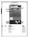
VISUAL INSPECTION: Before installing the unit, check the container
and machine for damage. A damaged container is an indicator that
there may be some damage to the machine. If there is damage to both
the container and machine, do not throw away the container. The dish-
machine has been inspected and packed at the factory and is expect-
ed to arrive to you in new, undamaged condition. However, rough han-
dling by carriers or others may result in there being damage to the unit
while in transit. If such a situation occurs, do not return the unit to
Jackson; instead, contact the carrier and ask them to send a repre-
sentative to the site to inspect the damage to the unit and to complete
an inspection report. You must contact the carrier within 48 hours of
receiving the machine. Also, contact the dealer through which you pur-
chased the unit.
UNPACKING THE DISHMACHINE: Once the machine has been
removed from the container, ensure that there are no missing parts
from the machine. This may not be obvious at first. If it is discovered
that an item is missing, contact Jackson immediately to have the miss-
ing item shipped to you.
LEVEL THE DISHMACHINE: The dishmachine is designed to oper-
ate while being level. This is important to prevent any damage to the
machine during operation and to ensure the best results when wash-
ing ware. The unit comes with adjustable bullet feet, which can be
turned using a pair of channel locks or by hand if the unit can be
raised safely. Ensure that the unit is level from side to side and from
front to back before making any connections.
PLUMBING THE DISHMACHINE: All plumbing connections must
comply with all applicable local, state, and national plumbing codes.
The plumber is responsible for ensuring that the incoming water line
is thoroughly flushed prior to connecting it to any component of the
dishmachine. It is necessary to remove all foreign debris from the
water line that may potentially get trapped in the valves or cause an
obstruction. Any valves that are fouled as a result of foreign matter left
in the water line, and any expenses resulting from this fouling, are not
the responsibility of the manufacturer.
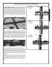
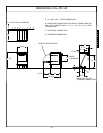
CONNECTING THE DRAIN LINE: The JPX-140 model covered in
this manual has a gravity discharge drain. Remove the drain plug from
the tub and the unit will drain itself. The unit comes with a flexible drain
hose that should be connected to the drain. The drain hose connec-
tion must drain downward and away from the machine.
The drain for the JPX-160 & JPX-200, is a pumped discharge drain.
Both of these dishmachines must be drained into a stand pipe (like a
household washing machine). If they are not, they will siphon them-
selves empty. The stand pipe for the JPX-160 is between 20 and 24
inches tall. The stand pipe for the JPX-200 is between 24 and 28 inch-
es tall. All piping from the machine to the drain must be a minimum 1”
I.P.S. and shall not be reduced.
There must also be an air gap between the machine drain line and the
floor sink or drain. If a grease trap is required by code, it should have
a flow capacity of 5 gallons per minute.
PRIMING THE DRAIN LINE: For the JPX-160 and JPX-200 models,
prime the drain pump before use when the machine is full of water.
Lower the end of the drain hose and allow some water to drain from
the hose. Raise the end of the hose and connect it to its installation
position.
WATER SUPPLY CONNECTION: Ensure that you have read the sec-
tion entitled “PLUMBING THE DISHMACHINE” above before pro-
ceeding. Install the water supply line (1/2” pipe size minimum) to the
to the vacuum breaker on the back of the machine. For ease of ser-
vice, the final water line connection to the machine should be using a
length of flexible hose, suitable for the pressure and temperature of
the incoming water. It is recommended that a water shut-off valve be
installed in the water line between the main supply and the machine
to allow access for service.
The water supply line is to be capable of 20 A5 PSI “flow” pressure
at the recommended temperature indicated on the data plate.
In areas where the water pressure fluctuates or is greater than the
recommended pressure, it is suggested that a water pressure regula-
tor be installed. The JPX series units do not come with water pressure
regulators as standard equipment.
Do not confuse static pressure with flow pressure. Static pressure is
the line pressure in a “no flow” condition (all valves and services are
closed). Flow pressure is the pressure in the fill line when the fill valve
is opened during the cycle.
It is also recommended that a shock absorber (not supplied with the
JPX series units) be installed in the incoming water line. This prevents
line hammer (hydraulic shock), induced by the solenoid valve as it
operates, from causing damage to the equipment.
PLUMBING CHECK: Slowly turn on the water supply to the machine
after the incoming fill line and the drain line have been installed.
Check for any leaks and repair as required. All leaks must be repaired
prior to placing the machine in operation.
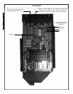
ELECTRICAL POWER CONNECTION:Electrical and grounding con-
nections must comply with the applicable portions of the National
Electrical Code ANSI/NFPA 70 (latest edition) and/or other electrical
codes.
Disconnect electrical power supply and place a tag at the disconnect
switch to indicate that you are working on the circuit.
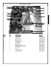
Refer to the data plate for machine operating requirements,
machine voltage, total amperage load and serial number.
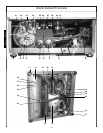
To install the incoming power lines for the JPX-140, route the power
lines through the grommet located in the rear AT THE TOP OF THE
MACHINE.
WARNING: do not attempt to route incoming power lines
to the dispenser terminal block located at the bottom of
the JPX-140! Contact your authorized Jackson service agency or
Jackson technical service if there are any questions.
To install the incoming power lines for the JPX-160 & JPX-200 route
the power lines through the grommet located at the rear of the
machine towards the bottom. Install the service wires (L1, L2 &
Ground) to the appropriate terminals on the terminal block. It is rec-
ommended that “DE-OX” or another similar anti-oxidation agent be
used on all power connections.
VOLTAGE CHECK: Ensure that the power switch is in the OFF posi-
tion and apply power to the dishmachine. Check the incoming power
at the terminal block and ensure it corresponds to the voltage listed on
the data plate. If not, contact a qualified service agency to examine
the problem. Do not run the dishmachine if the voltage is too high or
too low. Shut off the service breaker and mark it as being for the dish-
machine. Advise all proper personnel of any problems and of the loca-
tion of the service breaker. Replace the control box cover and tighten
down the screws.
INSTALLATION INSTRUCTIONS
1
I
N
S
T
R
U
C
T
I
O
N
S