


Conveyor Motor Replacement Instructions 07610-003-20-17 Rev. A
Issued: 03-14-2006 Revised: N/A
MAINTENANCE INSTRUCTIONS
REPLACING CONVEYOR MOTOR
2
The instructions provided here are for maintenance per-
sonnel only. Unauthorized persons should not attempt any of the
steps contained in these instructions.
Warning: many of the instructions and steps within
this document require the use of tools. Only authorized per-
sonnel should ever perform any maintenance procedure on
the dishmachine!
PREPARATION
1. Power must be secured to the unit at the service break-
er. Tag or lock out the service breaker to prevent accidental or
unauthorized energizing of the machine.
2. Ensure that incoming water to the machine is secured
either by use of a shut-off valve or disconnecting the incoming
water line.
3. Ensure that the dishmachine has been completely
drained of water and has been allowed to cool down prior to begin-
ning this maintenance procedure.
TOOLS REQUIRED
The following tools will be needed to perform this mainte-
nance evolution:
1. 7/16” socket and ratchet with extension
2. 9/16” socket and ratchet with extension
3. 5/16” Allen wrench
4. 5/16” nutdriver
5. Large flathead screwdriver
6. Small flathead screwdriver
TIME REQUIRED
It is estimated that it will take (1) person one and a half
hours to perform this task, not including all of the items indicated in
the section entitled “PREPARATION”.
IMPORTANT NOTES
1. Read these instructions thoroughly before attempting
this maintenance procedure. Become familiar with the parts and
what actions need to be taken. This will save time in the long run!
2. The procedures demonstrated in this manual are
shown being performed on an AJ-44 rack conveyor dishmachine.
The actual maintenance steps, however, apply to any wash, pre-
wash or power rinse motor found on a Jackson rack conveyor dish-
machine.
3. These basic instructions will apply to all prewash, wash
and power rinse motors found on AJ, TS and TSC series
machines.
STEPS
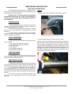
1. Remove the (4) nuts holding the mounting plate in position.
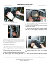
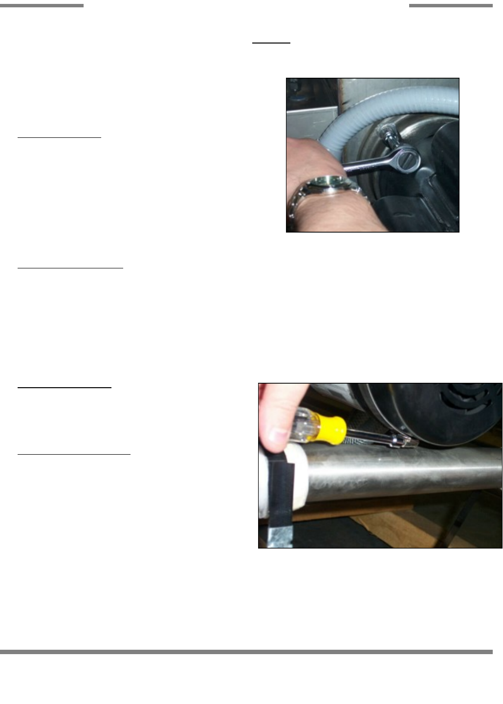
2. Loosen the band clamp on the back end of the motor.
3. With the band clamp loosened, carefully remove it from the back
end of the motor. Once the clamp is removed, examine it to deter
-
mine if it needs to be replaced as well. If it is broken in any spots
or shows signs of metal fatigue, it is best to order a new one. The
purpose of the clamp and the attached support bracket is to keep
the weight of the motor from pulling on the tub, damaging it. It is
absolutely necessary that this component be replaced once the
maintenance procedure is completed.
Removing the mounting plate nuts with the 9/16” socket
Loosening the band clamp on the back end of the motor.