


9
ANTI-TIP DEVICE INSTALLATION
INSTRUCTIONS
NOTE: A risk of range tip over exists if the appliance is
not installed in accordance with the installation
instructions provided. The proper use of this device
minimizes the risk of TIP-OVER. In using the device the
consumer must still observe the safety precautions as
stated in the USE and CARE MANUAL and avoid using
the oven door and/or kick plate as a step stool.
Installation instructions are provided for wood and cement
in either floor or wall. Any other type of construction may
require special installation techniques as deemed
necessary to provide adequate fastening of the ANTI-TIP
bracket to the floor or wall.
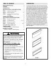
Included Parts
Included with this kit are: (4) #10 x 2² wood screws and
(1) Anti-tip bracket.
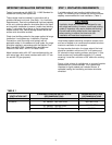
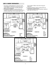
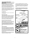
Wood Construction
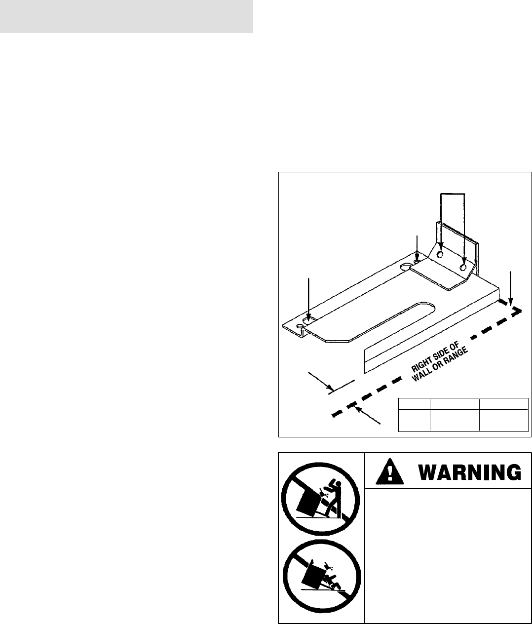
Place the bracket against the back wall, into the right rear
corner where the range is to be located. Leave a gap
between the wall (or side of range) and the bracket per
dimension “A” (see chart). Drill (2) 1/8² diameter pilot
holes in the center of the small holes. A nail or awl may
be used if a drill is not available. Fasten the bracket
securely to the floor and wall (see illustration).
Concrete Or Cement Construction
Hardware required: (2) sleeve anchors, lag bolts, and
washers (not provided). Locate the bracket as described
above. Drill the recommended size holes for the
hardware. Install the sleeve anchors into the holes and
then install the lag bolts through the bracket. The bolts
must be properly tightened as recommended for the
hardware. Fasten the bracket securely to the floor and
wall.
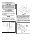
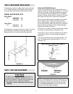
Range Installation
After the anti-tip bracket has been installed, complete
Steps 4-6 before sliding the range into position. Align
the range to its designated location and slide it back into
position. Make sure that the leveling foot is fully inserted
into and secured by the anti-tip bracket. To gain access to
the anti-tip bracket from the front of the range, remove the
kick plate by removing the (2) screws used to secure the
kick plate (Figure 5).
NOTE: Ensure that power is disconnected from the
range before the kick plate is removed.
For SAFETY CONSIDERATIONS as well as optimum
performance adjust the range so that it is level. This may
be checked by placing a spirit level or a large pan of water
on the cooktop or the oven rack. Slide-in ranges require
total removal from cabinet before an adjustment can be
made.
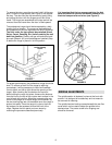
To check the range for proper installation of the anti-tip
bracket: Use a flashlight and look underneath the bottom
of the range to see that one of the rear leveling legs is
engaged int eh bracket slot.
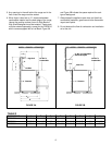
(2) Wood Screws into Back Wall
(ALL Installations)
(2) Small Holes For
Wood Installations
(2) Large Holes For
Concrete Installations
Back
Wall
DIMENSION A
A=
Model
Series
7/8²
PRG3010
5/8²
PRG3610
PRG4810
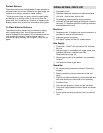
· ALL RANGES CAN TIP AND
CAUSE INJURIES TO
PERSONS.
· INSTALL ANTI-TIP DEVICES
PACKED WITH RANGE.
· FOLLOW ALL INSTALLATION
INSTRUCTIONS.