10
After the above operation, the burner will produce a
stable, steady blue flame of minimum size. The setting
should be checked by turning knob from high to low
several times without extinguishing the flame.
The above operation will automatically provide the proper
flame size at medium setting.
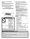
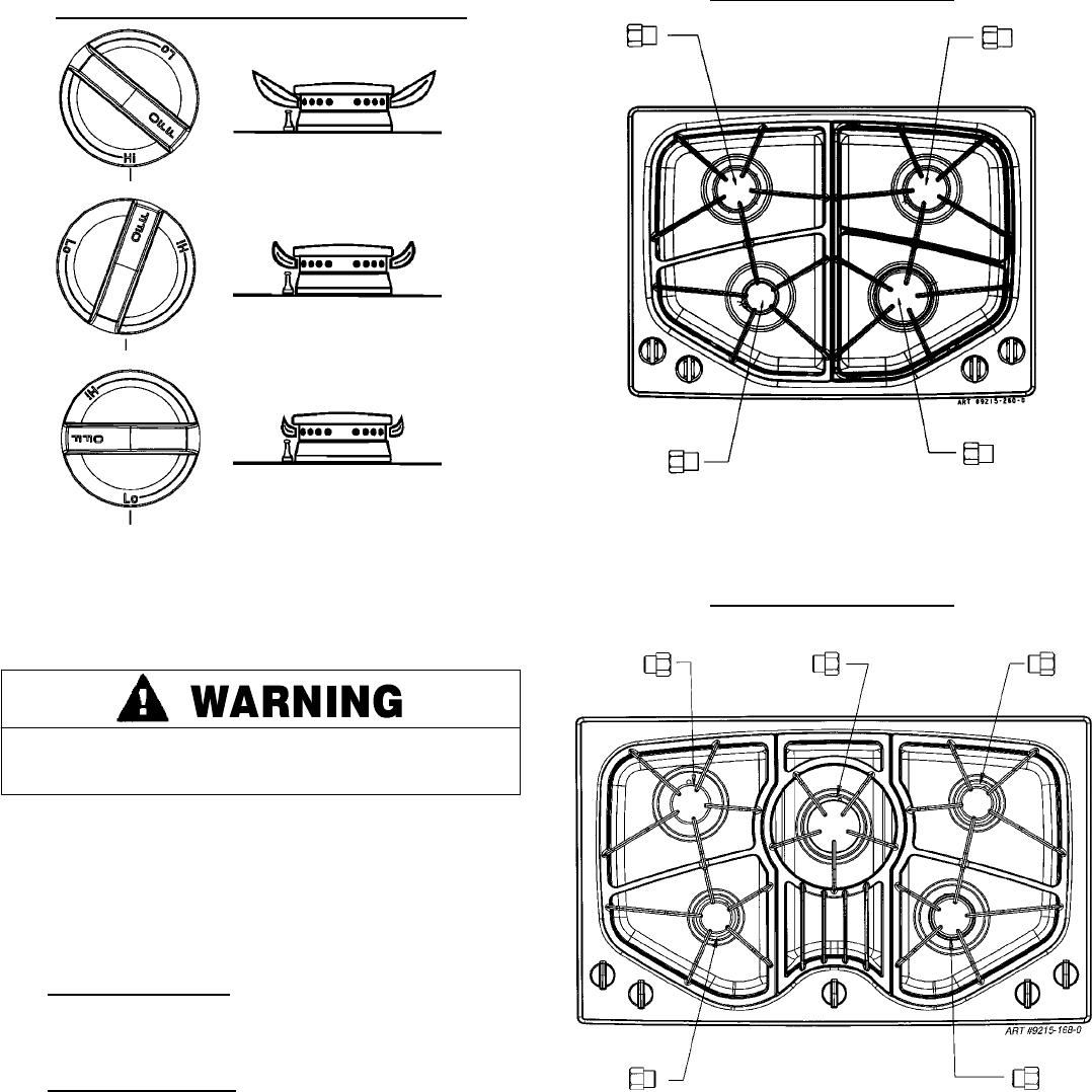
After Conversion Steps A, B and C have been completed,
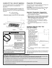
check the appearance of each burner flame at the Hi and
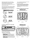
Lo settings against figure 14. If the flames appear too
large or too small, review each step to make sure it was
completed correctly.
FIGURE 14
FLAME APPEARANCE AT HI AND LO
To Convert Appliance For Use With
Natural Gas
Electrical power and gas must b e turned of f
prior to conversion.
If this appliance has been converted for use with LP gas,
each of the following modifications must be performed to
convert the unit back to natural gas.
A. REPLACE ALL ORIFICE SPUDS.
1. Perform Steps 1 and 2 on page 8.
2. JGC8430 - 30
²
²²
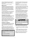
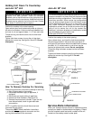
² Unit - Remove chokes from the left
rear, right rear and right front orifice holders (see
figures 10 and 11). As required a simple paper clip
can be used to remove the left and right rear choke.
JGC8536 - 36
²
²²
² Unit - Remove chokes from the left
rear, center andright front orifice holder (see figures 10
and 11). As required a simple paper clip can be used
to remvoe the left front and rear choke.
3. Perform Step 3 on page 8.
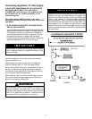
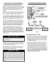
4. For Step 5: Locate the brass natural gas orifice
spuds that were originally installed in this appliance
before its conversion for use with LP gas. Observe
the number on each of the spuds and note the
correct burner location for each spud as shown in
figure 15 or 16.
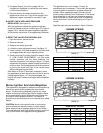
Installation Of Natural Gas Orifice Spuds
FIGURE 15
4 BURNER MODEL (30² WIDE)
1.45
1.55
1.07
1.90
FIGURE 16
5 BURNER MODEL (36
² WIDE)
1.47 1.90 1.07
1.07 1.66


