6
Alternative Piping Methods To
Connect Appliance To Gas Supply
A TRAINED SERVICEMAN OR GAS APPLIANCE
INSTALLER MUST MAKE THE GAS SUPPLY
CONNECTION. Leak testing of the appliance shall
be conducted by the installer according t o the
instructions given.
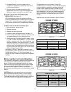
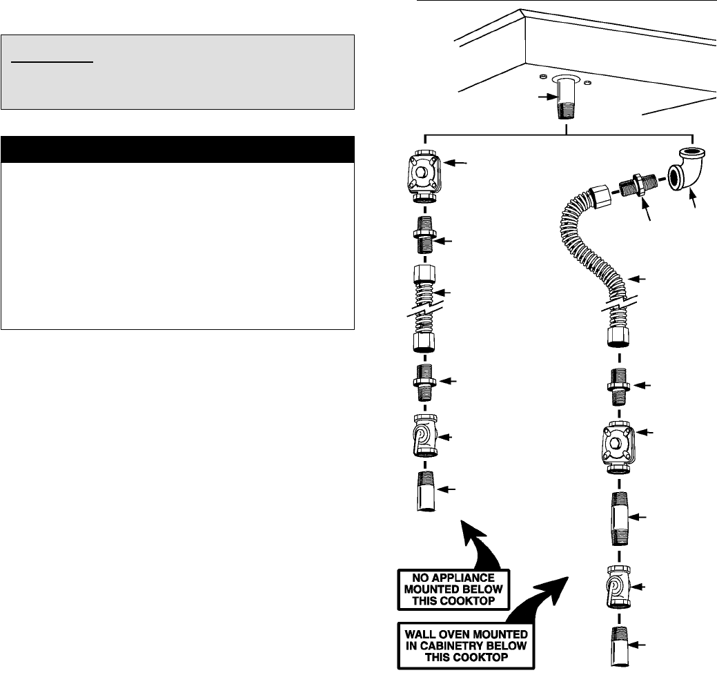
Unless prohibited by local codes or ordinances, a new
A.G.A. - Certified, flexible metal appliance connector may
be used to connect this appliance to its gas supply. The
connector must be no more than 5 feet in length. Per
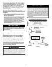
figure 5, use appropriate flare union adapter at each end
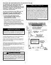
of the flexible connector. If a flexible connector is used
assure that both the appliance pressure regulator and
manual shut-off valve are joined solidly to other
permanent hard piping (either gas supply or the appliance
manifold) so as to be physically stationary. See
illustrations below:
CAUTION: Do not attempt to attach the flexible
connector directly to an external pipe thread.
Connection requires flare union adapters.
IMPORTANT
Apply a non-corrosive leak detection fluid to all joints and
fittings in the gas connection between the supply line
shut-off valve and the range. Include gas fittings and
joints in the range if connections were disturbed during
installation. Check for leaks! Bubbles appearing a round
fittings and connections will indicate a l eak. If a leak
appears, turn off supply line gas shut-off valve, tighten
connections, turn on the supply line gas shut off valve,
and retest for leaks. Never test for gas leaks with a n open
flame.
Pressure Testing
The appliance must be isolated from the gas supply
piping system by closing its individual manual shut-off
valve during any pressure testing of the gas supply piping
system at test pressures equal to or less than 1/2 PSIG
(3.5 kPa).
This appliance, as well as its individual shut-off valve,
must be disconnected from the gas supply piping system
during any pressure testing of the system at test
pressures in excess of 1/2 PSIG (3.5 kPa).
When checking appliance regulator function, make certain
pressure of natural gas supply is between 6 and 14
inches of water column or, if converted for LP gas,
between 11 and 14 inches.
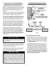
FIGURE 5
ILLUSTRATIVE ALTERNATIVE PIPING
3/8² N.P.T.
Elbow
3/8² N.P.T. Flexible
Appliance Connector
(5 ft. max.)
1/2² N.P.T. Flexible
Appliance Connector
(5 ft. max.)
Appliance Pressure
Regulator, Supplied
(Observe directionality
of Gas Flow)
Flare Union Adaptor
Flare Union Adaptor
Gas Shut-Off Valve
1/2² N.P.T. Pipe
(Stationary Supply Pipe)
Flare Union
Adaptor
Flare Union Adaptor
Appliance Pressure
Regulator, Supplied
(Observe
directionality of Gas
Flow)
1/2² N.P.T. Pipe
Nipple
Gas Shut-Off Valve
1/2² N.P.T. Pipe
(Stationary Supply
Pipe)
Manifold
Entrance


