


8
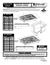
Converting Appliance For Use
With LP Gas
Propane conversion is to be performed by a JENN-AIR
AUTHORIZED SERVICER (or other qualified agency) in
accordance with the manufacturer’s instructions and all
codes and requirements of the authority having
jurisdiction. Failure to follow i nstructions could result in
serious injury or property damage. The qualified agency
performing this work assumes responsibility for this
conversion.
Electrical power and gas must b e turned of f
prior to conversion.
This appliance was adjusted at the factory for use with
natural gas. To convert it for use with LP gas (propane or
butane), each of the following modifications must be
performed: (A, B, and C)
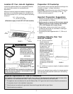
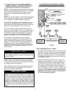
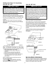
A. REPLACE ALL ORIFICE SPUDS
Step 1: Remove the grates and burner caps.
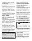
Step 2: Remove burner base by removing 2 (T-15)
6-lobe screws. (See figure 7). Leave spark wire
attached to base.
Step 3: Firmly press 9/32² (or 7mm) nut driver over
the orifice spud (figure 7) and loosen spud by turning
counterclockwise. Carefully lift nut driver out of burner
throat. Orifice spud should be captured in the recess.
Repeat this step for each burner.
FIGURE 7
REMOVAL OF ORIFICE
SPUD
SPARK WIRE
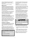
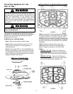
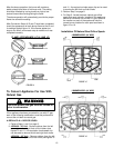
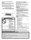
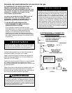
FIGURE 8
INSTALLATION OF LP ORIFICE SPUDS & CHOKES
.91 1.14
.64
.97
.64
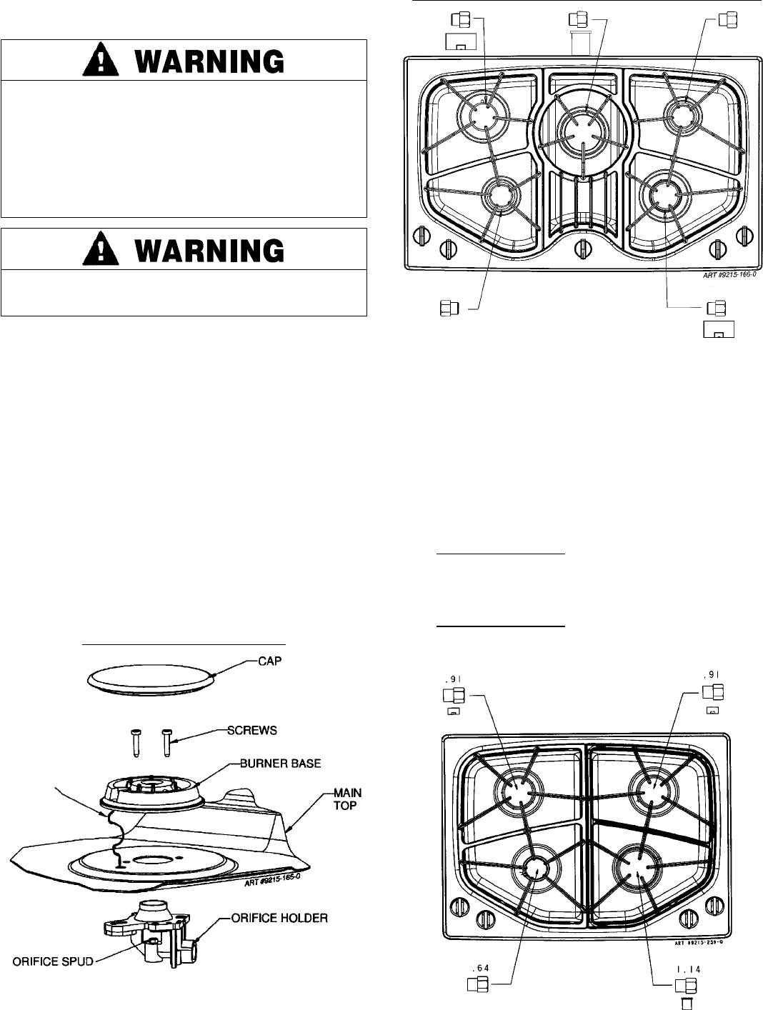
Step 4: Locate the LP orifice spud packet included in
the literature packet. The spuds have small numbers
stamped on the side. This number codes the orifice
diameter and its correct burner location. Figures 8 and
9 show the correct LP orifice spud location. There will
be extra spuds that are not required for the JGC8430
installation.
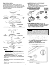
Step 5: Carefully install the orifice spud in the
appropriate burner throat by turning clockwise to
tighten. Tighten to a torque of 15 to 20 inch-lbs.
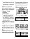
Step 6:
JGC8430 - 30
²
²²
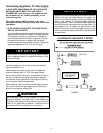
² Unit - Place 9.1k/10.5k burner
choke(s) into right rear and left rear (see figure 9)
orifice holder with chamfer facing down (see figure
10).
JGC8536 - 36
²
²²
² Unit - Place 9.1k/10.5k burner
choke(s) into right front and left rear orifice holder
with chamfer facing down (see figure 10).
FIGURE 9