


4
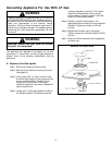
Installation Of Appliance
This appliance was adjusted at the factory for use with
natural gas. If, at any time, this appliance is to b e used
with a different type of gas, all of the conversion
adjustments must be made by a qualified s ervice
technician before attempting to operate the cooktop on
that gas. Natural gas should b e s upplied to t he applianc e
pressure regulator at a line pressure between 6 and 14
inches of water column or, if converted for LP gas,
between 11 and 14 inches.
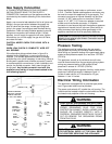
If the line pressure supplying the appliance pressure
regulator exceeds 14² W.C. (any gas), an external
regulator must be installed i n the gas line ahead of the
appliance regulator to reduce the pressure to no more
than 14² W.C. Failure to do this c an result in malfunction
and damage to the applianc e.
WARNING
Insure this appliance is adjusted for the type of gas
supplied to it and that the gas s upply p ressure to the
appliance regulator is within the proper pressure range.
Do not remove protective cap from pipe stub at manifold
entrance until ready to join gas supply piping to applianc e.
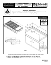
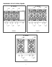
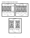
The Countertop Cutout and Cabinet Front Cutout should
be prepared according to the illustrations on pages 1 and
2.
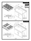
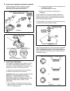
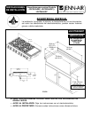
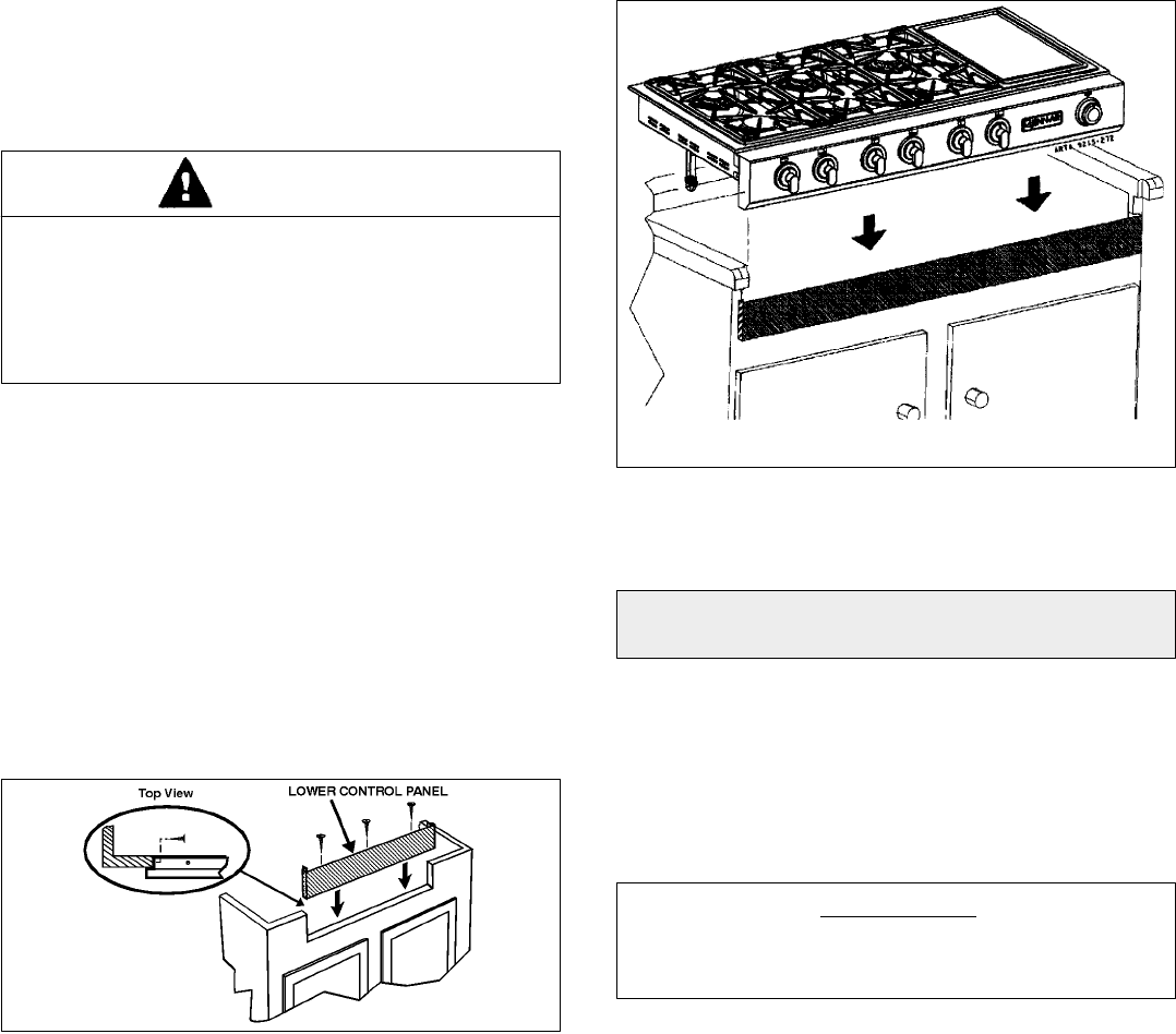
Install the Lower Control Panel in t he bottom of the
Cabinet Cutout as shown using screws from Hardware
pack (Figure 6).
FIGURE 6
Position unit in the Countertop Cutout. Main Control Panel
should overlap top of Lower Control Panel as shown
(Figure 7).
FIGURE 7
NOTE: For some cabinet styles, it may be necessary to
reinforce the front of the cabinet by attaching a b race from
front to rear inside the cabinet under the Burner Box.
CAUTION: Warranty is void on JENN-AIR equipment
installed other than as recommended by manufacturer.
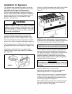
Join the appliance pressure regulator supplied with this
appliance to the entrance threads of the Gas Manifold.
The appliance regulator is marked with a d irectional arrow
indicating correct direction of gas flow. Ensure the
appliance regulator is installed with the arrow pointing
toward the gas m anifold entrance. Tighten the appliance
regulator to 20 to 30 ft-lbs of torque.
IMPORTANT
Never tighten to more than 35 ft-lbs of torque. Always use
an approved pipe joint compound resistant to the action
of LP gas.
Install the appliance in its counter cutout.
Make the gas connection to the inlet of the appliance
pressure regulator with 1/2² male pipe threads.
Install a manual s hut-off valve in an accessible location in
the gas line ahead of the appliance p ressure regulator
and external to this appliance for the purpose of turning
on or shutting off gas to the appliance.
Make additional pipe connections as necessary ahead of
the shut-off valve to the gas s upply source. Assure all
pipe joint connections are gas tight.