


5
Gas Supply Connection
A TRAINED SERVICEMAN OR GAS APPLIANCE
INSTALLER MUST MAKE THE GAS SUPPLY
CONNECTION. Leak testing of the appliance shall be
conducted by the installer according to the instructions
below.
Apply a non-corrosive leak detection fluid to all joints and
fittings in the gas connection between the supply line
shut-off valve and the r ange. Include gas fittings and
joints in the range if connections were disturbed during
installation. Check for leaks! Bubbles appearing around
fittings and connections will indicate a leak. If a leak
appears, turn off supply line gas shut-off valve, tighten
connections, turn on the s upply line gas shut-off valve,
and retest for leaks.
CAUTION: NEVER CHECK FOR LEAKS WITH A
FLAME.
WHEN LEAK CHECK IS COMPLETE, WIPE OFF
ALL RESIDUE.
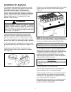
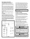
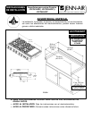
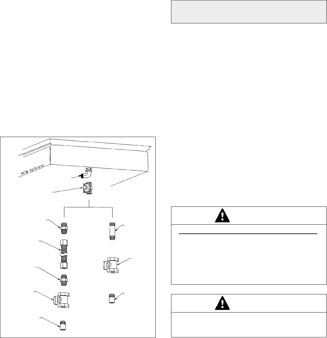
If the alternative piping method shown in figure 8 is
selected for the installation, no ground joint union is
required. (The flexible appliance connector illustrated
provides the union joints necessary for servicing.) When a
dividing wall is pr esent and a flexible connector is used it
is recommended for convenience, in both installation and
service, the flexible connector, itself, pass through the
dividing wall. Any flexible connector used with this
appliance must satisfy all requirements stated in the
text following figure 8.
FIGURE 8
MANIFOLD PIPE
GAS
SHUT-OFF
VALVE
APPLIANCE PRESSURE
REGULATOR, SUPPLIED
(OBSERVE DIRECTION
OF GAS FLOW ARROW)
FLARE
UNION
ADAPTOR
FLEXIBLE
APPLIANCE
CONNECTOR
(5 FT. MAX)
FLARE
UNION
ADAPTOR
1/2² NPT
PIPE
1/2² NPT
PIPE
1/2² NPT
PIPE
NIPPLE
GAS
SHUT-OFF
VALVE
Unless prohibited by local codes or ordinances, a new
A.G.A. - Certified, flexible metal appliance connector may
be used to connect this appliance to its gas supply. The
connector must have an internal diameter not less than
nominal 1/2² NPT pipe and be no more than 5 feet in
length. A 1/2² NPT x 1/2² flare union adapt er is required
at each end of the flexible connector. If a flexible
connector is used a ssure that both the appliance pressure
regulator and manual shut-off valve are joined solidly to
other permanent hard piping ( either gas supply o r the
appliance manifold) so as to be phy sically stationary.
CAUTION: Do not attempt to attach the flexible connector
directly to an external pipe thread. Connection requires
flare union adapt ers.
Pressure Testing
The appliance must be isolated from the gas supply
piping system by closing its individual manual shut-off
valve during any pressure testing of the gas supply piping
system at test pressures equal t o or less than 1/2 PSIG
(3.5 kPa).
This appliance, as well as its individual shut-off valve,
must be disconnected from the gas supply piping system
during any pressure testing of the system at test
pressures in e xcess of 1/2 PSIG (3.5 kPa).
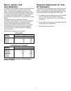
When checking appliance regulator function, make certain
pressure of natural gas supply is between 6 and 14
inches of water column or, if converted for LP gas,
between 11 and 14 inches.
Electrical Wiring Information
This appliance is equipped with a grounded type power
cord. A grounded outlet must be p rovided.
The power cord extends 45² outside the unit housing. The
outlet should be located inside the cutout width and below
the lowest most projection of the unit housing.
ELECTRICAL GROUNDING INSTRUCTIONS
THIS APPLIANCE IS EQUIPPED WITH A THREE
PRONG GROUNDING PLUG FOR YOUR
PROTECTION AGAINST SHOCK HAZARD AND
SHOULD BE PLUGGED DIRECTLY INTO A
PROPERLY GROUNDED R ECEPTACLE. DO NOT
CUT OR REMOVE THE GROUNDING PRONG
FROM THIS PLUG.
WARNING
THIS APPLIANCE MUST BE DISCONNECTED FROM
ITS ELECTRICAL SUPPLY AT THE WALL RECEP-
TACLE BEFORE SERVICING THE APPLIANCE.
WARNING