Step4
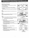
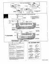
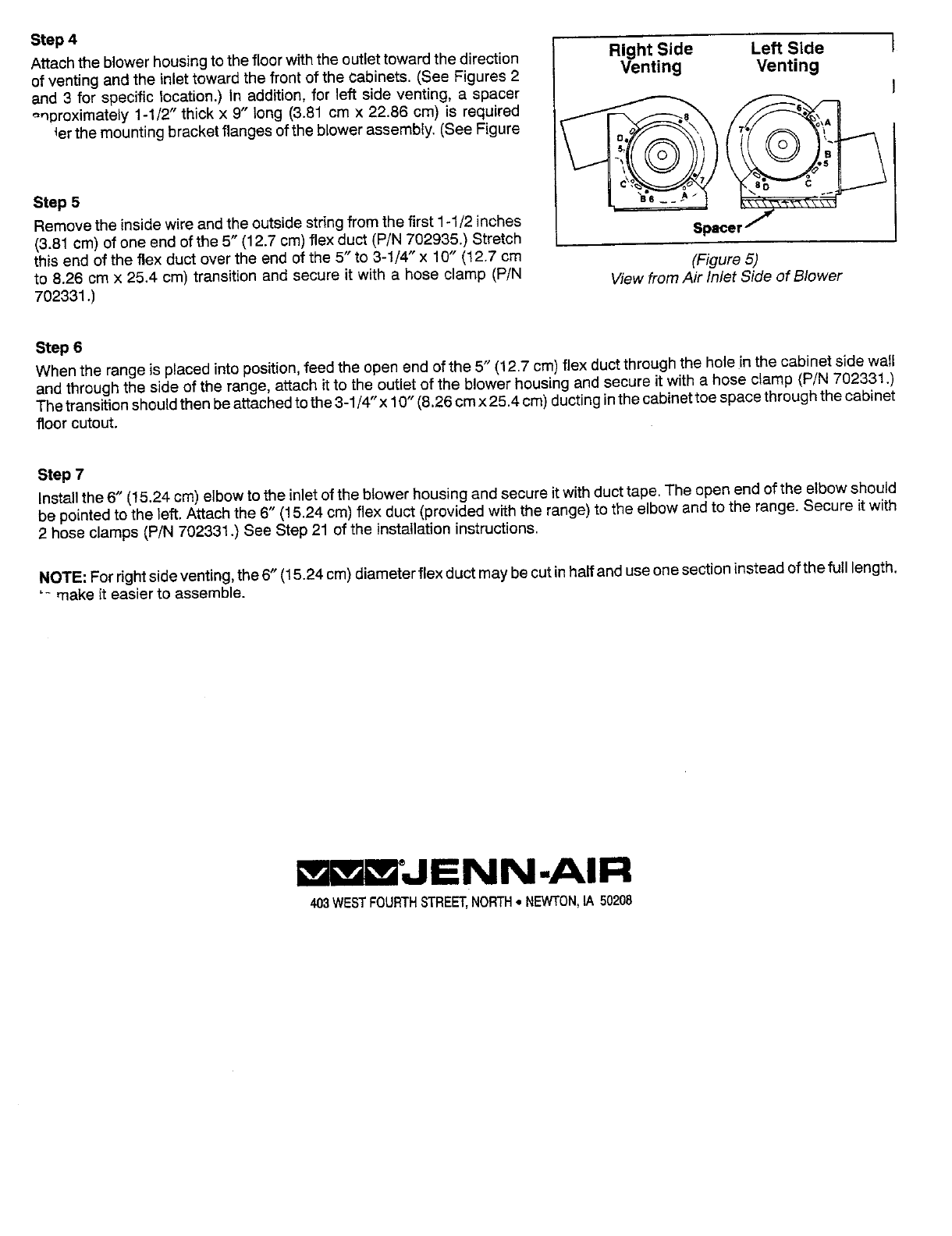
Attachthe blowerhousingtothefloorwiththe outlettoward thedirection Right Side Left Side I
of venting andthe inlettoward the front of the cabinets. (See Figures2 Venting Venting
and 3 for specific location.) in addition,for left side venting, a spacer I
_,_proximately1-1/2" thick x 9" long (3.81cm x 22.86 cm)is required __
{erthemountingbracketflanges ofthe blowerassembly.(SeeFigure
Step5
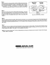
Removethe inside wire andtheoutsidestringfrom thefirst 1-1/2inches Spacer/
(3.81cm) of oneend of the 5" (12.7cm)flexduct (P/N702935.)Stretch
this end of the flex duct over the end of the 5" to 3-1/4" x 10" (12.7cm (Figure5)
to 8.26 cm x 25.4 cm) transitionand secure it witha hose clamp (P/N ViewfromAir Inlet Side of Blower
702331.)
Step 6
Whenthe rangeis placedinto position,feed the open endofthe 5" (12.7cm)flex ductthroughthe hole inthe cabinet side wall
and throughthe sideof the range, attach itto the outletof the blower housingand secureit with a hose clamp (P/N 702331.)
Thetransitionshouldthen beattachedtothe 3-1/4"x 10" (8.26cmx 25.4cm)ductinginthecabinettoespacethroughthe cabinet
floor cutout.
Step 7
Installthe 6" (_5.24cm)elbowto the inlet of the btowerhousingand secureit withducttape. The open endofthe elbowshould
be pointedto the left.Attachthe 6" (15.24cm)flex duct (providedwiththe range)to the elbowandto the range.Secure it with
2 hoseclamps (P/N 702331.) See Step21 of the installationinstructions.
NOTE:Forrightsideventing,the 6" (15.24cm)diameterflexductmay becutinhalfanduseonesectioninsteadof thefull length.
"- makeit easier to assemble.
'JENN-AIR
403WESTFOURTHSTREET,NORTH• NEWTON,IA 50208


