


13
To Convert Surface Burners
1. Remove Natural gas orifice hoods. Locate the LP gas orifice
hoods from the package attached to the outer plenum area of
this appliance.
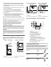
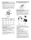
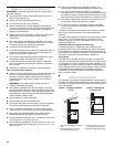
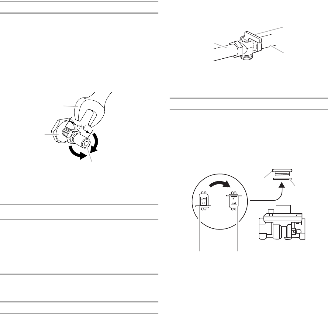
2. To convert from Natural gas to LP gas, apply a ½" open-end
wrench to hex section of orifice hood. Turn counterclockwise
to remove.
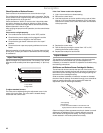
3. Replace with correct color-coded orifice hoods (supplied).
See the “LP Gas Orifice Hood Chart.” Turn clockwise to
install. Screw down the orifice hood so that the outer end of
the orifice hood is ¹¹⁄₁₆" from the face of the mounting spud.
See the following illustration.
LP Gas Orifice Hood Chart
4. Place Natural gas orifice in plastic parts bag for future use
and keep with package containing literature.
5. Repeat for the remaining burners.
Complete Installation
1. Refer to the “Make Gas Connection” section for properly
connecting the cooktop to the gas supply.
2. Refer to the “Burner Ignition” section for proper burner
ignition, operation, and burner flame adjustments.
IMPORTANT: You may have to adjust the “LO” setting for
each cooktop burner.
Checking for proper cooktop burner flame is very important.
The cooktop “low” burner flame should be a steady blue
flame approximately ¼" (0.64 cm) high.
3. Refer to the “Complete Installation” section of this manual to
complete this procedure.
Natural Gas Conversion
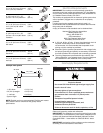
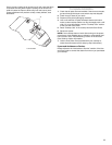
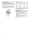
1. Turn manual shutoff valve to the closed position.
2. Unplug cooktop or disconnect power.
To Convert Gas Pressure Regulator
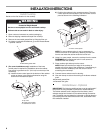
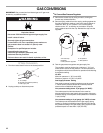
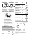
1. Remove the access cap by using a wrench, turning the
access cap counterclockwise.
2. Remove spring retainer from the cap by pushing against the
flat side of the spring retainer. Look at the spring retainer to
locate the “LP” or “NAT” position. Turn over the spring
retainer so the “NAT” is showing on the bottom. Snap the
spring retainer back into the cap. Reinstall the cap onto the
regulator.
3. Test the gas pressure regulator and gas supply line.
The regulator must be checked at a minimum 1" (2.5 cm)
water column above the set pressure. The inlet pressure to
the regulator should be as follows for operation and checking
the regulator setting:
Natural Gas:
Minimum pressure: 6" (15.2 cm) WCP
Maximum pressure: 14" (35.5 cm) WCP
Gas Supply Pressure Testing
Gas supply pressure for testing regulator must be at least
1" water column pressure above the manifold pressure
shown on the model/serial rating plate.
Line pressure testing above ½ psi gauge (14" WCP)
The cooktop and its individual shutoff valve must be
disconnected from the gas supply piping system during any
pressure testing of that system at test pressures in excess of
½ psi (3.5 kPa).
Line pressure testing at ½ psi gauge (14" WCP) or lower
The cooktop must be isolated from the gas supply piping
system by closing its individual manual shutoff valve during
any pressure testing of the gas supply piping system at test
pressures equal to or less than ½ psi (3.5 kPa).
A.½" open-end wrench
B.Orifice hood
C.Mounting spud
Burner BTU/hr Orifice Diameter
(inches)
Color
Left rear 7,500 #66 .033 Zinc
Left front 7,500 #66 .033 Zinc
Center rear 6,500 #68 .031 Red
Center front 9,000 #63 .037 Blue
Right rear 6,500 #68 .031 Red
Right front 9,000 #63 .037 Blue
Turn
clockwise
to tighten
Turn
counterclockwise
to remove
A
B
C
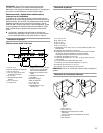
A.To cooktop
B. Shutoff valve (closed position)
C.Gas supply line
A.Access cap
B. Gasket
C.Gas pressure regulator
D. NAT position
E.LP position
A
B
C
A
B
CDE