


4
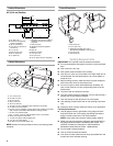
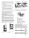
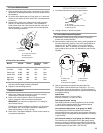
Product Dimensions
48" (121.9 cm) Cooktop
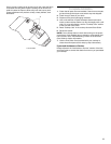
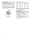
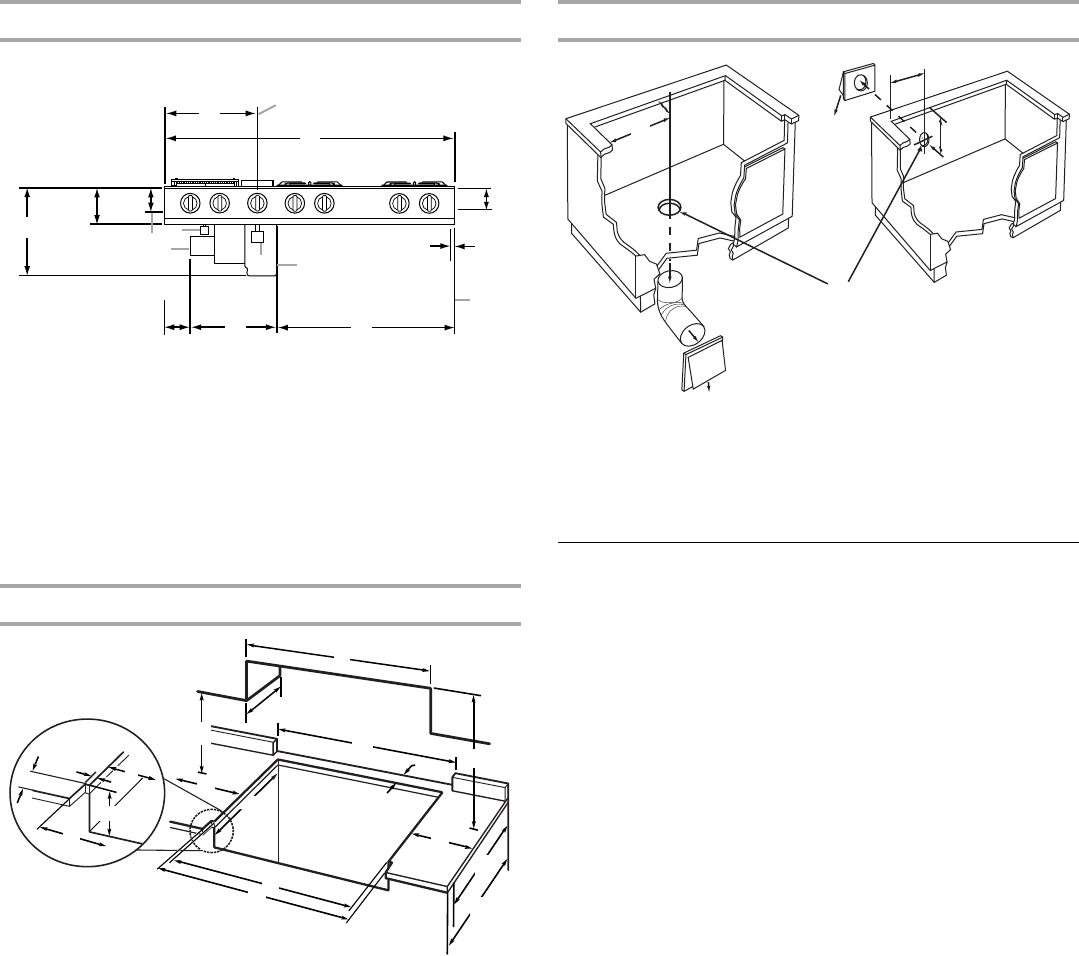
Cabinet Dimensions
NOTE: Access must be provided to remove and empty grease
container.
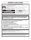
Cutout Dimensions
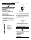
Venting Requirements
IMPORTANT: This cooktop must be exhausted outdoors.
■ Do not terminate the vent system in an attic or other enclosed
area.
■ Use a Jenn-Air
®
vent cap.
■ Vent system must terminate to the outside.
■ Use only a 6" (15.2 cm) round metal vent. Rigid metal vent is
recommended. For best performance, do not use plastic or
metal foil vent.
■ Before making cutouts, make sure there is proper clearance
within the wall or floor for the exhaust vent.
■ Do not cut a joist or stud unless absolutely necessary. If a
joist or stud must be cut, then a supporting frame must be
constructed.
■ The size of the vent should be uniform.
■ The vent system must have a damper. If roof or wall cap has a
damper, do not use damper supplied.
■ Use vent clamps to seal all joints in the vent system.
■ Use caulking to seal exterior wall or roof opening around the
cap.
■ Determine which venting method is best for your application.
For Best Performance:
■ Use 26-gauge minimum galvanized or 25-gauge minimum
aluminum metal vent. Poor quality pipe fittings can reduce
airflow. Flexible metal vent is not recommended.
NOTE: Local codes may require a heavier gauge material.
■ Metal duct may be reduced to 30-gauge galvanized steel or
26-gauge aluminized steel if allowed by local codes. This
reduction is based on information in the International
Residential Codes Section M1601.1 (2006 edition).
■ Do not install 2 elbows together.
■ Use no more than three 90° elbows.
■ If an elbow is used, install it as far away as possible from the
hood’s vent motor exhaust opening.
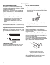
A. 15" (38.1 cm)
B.Centerline of appliance
pressure regulator
C.46
¹³⁄₁₆
" (118.9 cm)
D.3
⁵⁄₁₆
" (8.4 cm) bottom of
burner box
E.¾" (1.9 cm)
F. End of burner box
G.28
¹¹⁄₁₆
" (72.9 cm)
H.14" (35.6 cm)
I. Provide 2" (5.1 cm) min. cabinet
clearance to motor for cooling
purposes
J.Wire cover box
K.Appliance pressure regulator
L.Blower
M.Drain jar
N.Bottom of baffle
O.3
¹³⁄₁₆
" (9.7 cm)
P. 5¾" (14.6 cm)
R.15
¹³⁄₁₆
" (40.2 cm) min. clearance
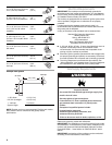
A.1¾" (4.5 cm) min.
B. 30" (76.2 cm) min.
C.48" (121.9 cm)
D.45¾" (116.2 cm)
E.46
¹³⁄₁₆
" (118.9 cm)
F. 18" (45.7 cm) min. clearance upper cabinet to countertop
G.22" (55.9 cm) cutout depth
H.8" (20.3 cm) min. distance on both sides of the cooktop to the side
wall or other combustible material above cooking surface
I.24" (61.0 cm) cabinet depth
J.5¾" - 9" (14.6 - 22.9 cm) cabinet depth to top of countertop
K.Notch to be equal on both sides
L.13" (33.0 cm) upper cabinet depth max.
M.1
¹⁄₁₆
" (2.7 cm) notch depth
N.25" (63.5 cm) countertop depth min.
A
B
C
D
E
F
G
H
I
J
K
L
M
N
O
P
R
B
C
A
E
F
G
I
J
K
C
E
H
L
H
D
D
N
M
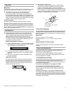
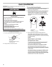
A.9
³⁄₈
" (23.8 cm)
B. 13
⁷⁄₁₆
" (34.1 cm)
C.Select appropriate duct cutout.
(See ducting installation instructions.)
D.13" (33.0 cm)
E. 9
³⁄₈
" (23.8 cm)
A
B
C
D
E