


6
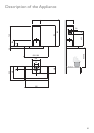
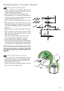
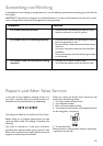
Fitting the Wall Brackets
• Draw a vertical line on the supporting wall up to the
ceiling, or as high as practical, at the centre of the area
in which the hood will be installed.
• Draw a horizontal line at 650 mm above the hob.
• Place bracket item 7.2.1 on the wall as shown about 1-2
mm from the ceiling or upper limit aligning the centre
(notch) with the vertical reference line.
• Mark the wall at the centres of the holes in the brack-
et.
• Place bracket item 7.2.1 on the wall as shown at X mm
below the first bracket (X = height of the upper chim-
ney section supplied), aligning the centre (notch) with the
vertical line.
• Mark the wall at the centres of the holes in the brack-
et.
• Draw a horizontal line through the vertical at 306mm
above the hob and mark two hole centres at 116mm
either side of the vetical line.
• Drill ø 8 mm holes at all the centre points marked.
• Insert the wall plugs (not supplied) in the holes.
• Fix the brackets using the screws (not supplied).
• Insert two screws into the two holes 116mm either side
of the vertical line and tighten leaving a space between
the underside of the screwhead and the wall of 5-6mm.
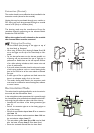
Note: If the hood is to be installed onto a hollow
construction or plaster or partition board wall
then special fixing screws will be required (not
supplied).
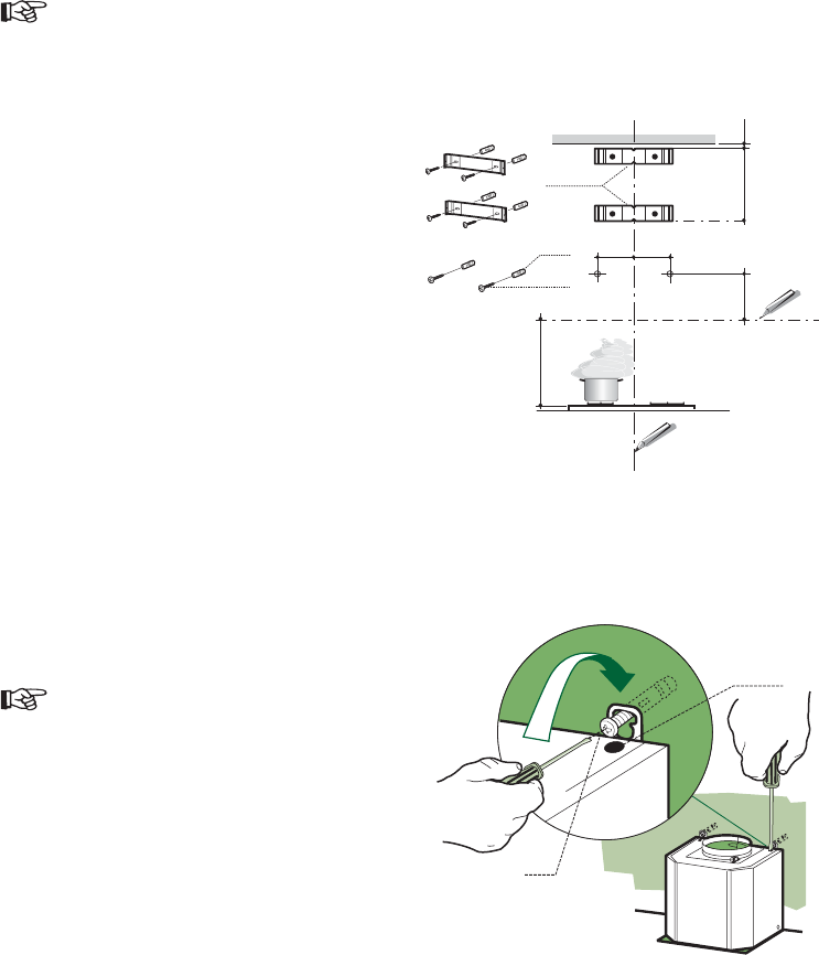
Fitting the Canopy Hood
• Before starting to fix the hood body, tighten the two
screws item Vr located on the top of the hood body.
• Hook the hood body onto the two screws item 12a.
• Fully tighten the screws item 12a.
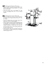
• Using a screw driver and spirit level, adjust the screws
item Vr until the hood body is level.
11
12a
306
X
116
1÷2
116
650 min.
7.2.1
12a
Vr
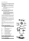
Installing the Cooker Hood