


DISASSEMBLY
You will need:
Adjustable wrench “Stubby” screwdriver
Standard pliers Standard screwdriver
Servicing should only be performed by qualified and licensed
service companies. Always disconnect the electrical power
cable before attempting any service
The filter maybe hot; use care while servicing. As a
safety precaution, it is recommended you drain oil from
the filter vessel before performing any servicing.
A. MELT AND/OR PUMP INDICATOR LIGHTS
Removal:
1. Disconnect filter from electrical power source.
2. Feel front end panel from bottom to locate rear of
defective indicator light. Note two tangs that extend
slightly beyond indicator light barrel diameter. Use a
standard pliers to squeeze tangs together and pull
indicator light free from panel. If indicator light doesn’t
release, squeeze tighter and break barrel to release
electrical leads. Discard broken pieces.
Replacement:
1. If necessary, clip off electrical leads as close as
possible to indicator light. If leads were clipped, trim
off insulation 1/8 inch from end.
2. With electrical leads extending through panel front,
press them into recesses at rear of replacement
indicator light to secure them in place. Press
indicator light into panel until tangs engage to secure
indicator light to panel.
B. MELT AND/OR PUMP ON/OFF SWITCH
Removal:
1. Disconnect filter from electrical power source.
2. Unscrew nut securing defective switch to panel.
Push switch in to release from panel. Remove
nameplate from front of panel.
3. Access to rear of switch through bottom hole under
front end panel.
4. Disconnect leads from switch. Tag leads as they are
disconnected to assure, during replacement, they are
reconnected to the proper switch terminals.
Replacement:
1. Connect tagged electrical leads to replacement
switch.
2. Insert replacement switch through panel from which
defective switch was removed. Insert nameplate over
toggle and secure to panel with nut supplied with
switch. Orient switch and tighten nut to secure in
desired position.
3. Plug in filter power cord and operate switch to verify
switch orientation corresponds to nameplate legend.
If not, loosen attaching nut and reorient nameplate
and/or switch as desired and retighten nut.
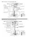
C. MELT CYCLE SENSOR
Removal:
1. Disconnect filter from electrical power source.
NOTE: Remove all oil from filter vessel. Filter must
be positioned on its end to access melt cycle
sensor.
2. Raise front (power cord) end of filter and rest filter on
oil absorbing rags on its back end.
3. Remove bottom cover attaching screws; remove
bottom cover.
4. Remove electrical leads from defective melt cycle
sensor.
5. Loosen heater element cover attaching nut adjacent
to melt cycle sensor sufficiently to release melt cycle
sensor and its retaining plate. Disengage melt cycle
sensor.
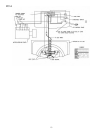
Replacement:
1. Orient replacement melt cycle sensor in its retaining
plate such that the metallic sensing surface will be in
direct contact with filter vessel. If necessary, reverse
orientation of retaining plate.
2. Position retaining plate under heater element and tab
on heater element cover with melt cycle sensor
sensing surface in direct contact with filter vessel.
Tighten loosened heater element attaching nut.
3. Attach removed electrical leads to melt cycle sensor.
Verify terminals are not in contact with any metallic
parts of filter vessel, heater cover or heater.
4. Secure bottom cover with removed attaching screws.
5. Position filter right-side-up and clean up oil absorbing
rags.
SERVICE
4