


11
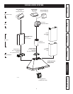
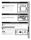
INSTALL THE HOOD
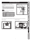
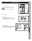
1. Construct wood wall framing that is fl ush with surface of wall
studs.
Wood wall framing must be at least 1/2” thick and 3” high.
Ensure to assemble wood wall framing to wall studs for a
solid installation.
Ensure the height of the framing will allow the mounting
bracket to be secured to the framing within the dimensions
shown (see illustration beside).
After wall surface is fi nished, carefully center and level the
hood mounting bracket over installation location. Secure it
to wall framing using 3 no. 8 x 1½” screws.
Using a level, draw a vertical line up to the ceiling starting
from the mounting bracket center.
WARNING: When cutting or drilling into wall,
do not damage electrical wiring and other
hidden utilities.
HD0374A
36¾” = BOTTOM OF HOOD 24” ABOVE COOKTOP
42¾” = BOTTOM OF HOOD 30” ABOVE COOKTOP
Warranty Safety CleaningOperation Installation Service Parts
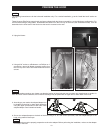
2. Center the upper fl ue mounting bracket with the center line
previously drawn and place it fl ush with the ceiling.
Use the upper fl ue mounting bracket as a template to mark
the position of its screws.
Drill the 3 screw holes using a 3/16” drill bit.
Insert the included drywall anchors into the drilled holes
(1 per hole).
Secure the upper fl ue bracket to the wall using 3 no. 8 x 3/4”
screws.
Ensure that the bracket is tight against the wall.
HD0377
C
L
CEILING
SCREW LOCATIONS
MOUNTING BRACKET
FLUSH WITH CEILING
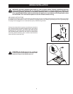
WARNING: BE CAREFUL when installing the decorative fl ue and hood, they may have sharp edges.
CAUTION: DO NOT REMOVE the protective plastic fi lm covering the decorative fl ue (upper & lower).
!
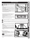
3. Align the hood and center it above the hood mounting
bracket. Gently lower the hood until it securely engages the
bracket.
Level the hood.
With the hood hanging in place, secure it to the wall through
both holes located in the inside upper back of hood using
2 no. 8 x 1½” screws.
Drill through both holes located in the inside lower back
of hood using a 3/16” drill bit. Insert the included drywall
anchors into the drilled holes (one for each hole). Secure
the hood to the wall using 2 no. 8 x 3/4” screws and
2 washers.
HD0380A
LOWER HOLES LOCATION
BACK OF THE HOOD
SIDE VIEW
Ø 3/16” TYP.
U
PPER HOLES LOCATION
!
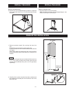
HORIZONTAL DISCHARGE ONLY:
4. Position the blower on the higher (A) or lower (B) back wall
discharge as determined previously.
Using a 5/16” socket, or a Robertson or a Phillips no. 2
screwdriver and the 4 previously removed screws, secure
the blower to the hood.
NOTE
In order to ease installation, before mounting the blower,
prepare the screw holes by screwing all 4 screws without
the blower, then remove and mount the blower.
HD0387
A
B
R
IGHT SIDE
MOUNTING
SCREW
LOCATION
5. Plug the blower back in and plug hood power cord into the
outlet.