


Read and understandthese instructions thoroughly before installing
beer dispenser.
ASSEMBLY
1. Carton Inventory
Unpack and inspect the parts. Make sure all items are present
and in good condition.
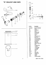
1 Draft arm assembly (Package includes 1 gasket for
draft arm and 1 washer for connectionto keg tapper)
1 CO2 regulator
1 CO2 cylinder
1 Keg tapper (Sankey type)
1 Cleaning kit
1 Pressure tube
2 Hose clamps
2 Keg supports (wooden plates)
1 CO2 cylinder retainer (spring)
1 Guard rail
1 Drip tray
4 Wheel casters
4 Hex head screws (5mm dia x 15mm long)
16 Machine screws (5mm dia x 12mm long)
8 Small screws (5mm dia x 10mm long)
2. Installcasters
a. Empty the cabinet and then lay down the beer dispenser
sidewaysso that the doorhingeside comesto the top.Be
careful not to cause dents or scratches on the cabinet.
Placing outer carton underneath the cabinet is
recommended.
b. Install casters to the four bottom corners of the cabinet
with the four machine screws (5mm dia x 12mm long)for
each caster.
c. Stand the cabinet upright.
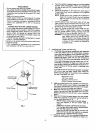
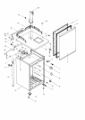
3. Install Draft Arm Assembly (See Fig. 1).
a. Slidegasket over wingnut on bottomof draft arm assem-
blybeer tube. Slide gasket upbeer tube to draftarm base.
Hex. Head
Screw
i
I
Draft Arm Assembly
Gasket
• / Small Screw
Guard Rail .,_ /
Fig 1.
b. Push wingnut and beer tube of draft arm assembly
through hole in top of cabinetuntil draftarm is restingon
cabinettop.
c. Alignholesin draftarm base withholes ingasket and pilot
holes in cabinet top,then securedraft arm to cabinet top
withfour hex head screws (5mm dia x 15mm).
4. Install Guard Rail (See Fig. 1).
a. Place guard rail on cabinet top and secureguard rail with
eight small screws.
INSTALLATION "
1. Installbeer dispenser on stronq,,lev_-IftnnLA_ia direct sun-
light, heatZJb'0_sa_"a_moi-sture. -
2. Connect to-120Vr- , out_et. Do not
use extension cord. Use __q,,_X_tb three-prong
grounded W'_ff'6"0t1"b.'t_"_ , .. ,.,
WARNING: Unless the _'d_O_"_gr-_ndingmethod'Js'io/lowed,
you are not _rotep_=d_,.agaim_-severe 'or lethal
sh0_k in'_h+_'eventofa shortcircuitof an electrical
cq.mponer=Lor_widngof beer dispenser.
TEMPERATURE CONTROL
1. Controlis locatedonrear. Firstset the control at NORMAL pos-
ition.Wait for 24 hours to check the temperature then adjust
temperature control, if needed.
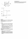
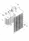
DEFROST
1. Beer dispenser will not require much defrosting since the
door opening is at a minimum. Defrost when V4inch frost is
built up on the cold plate. The best time to defrost is when
the keg is changed. To defrost, set temperature control at
OFF position and leave door open until ice melts. Defrost
water will accumulate at the bottom of interior cabinet
which can be absorbed with a sponge or towel.Do notus6
heating devices or sharp objects to speed defrosting
as this could damage cabinet liner of cold plate. Reset
temperature control after defrosting is completed.
INSTALLATION OF BEER SYSTEM
1.
Installing CO 2 Cylinder and CO2 Regulator
WARNING: CO2 GAS CAN BE DANGEROUS
Read front pages of "Draught Beer Facts" book in-
cluded in your cleaning kit for safety precautions
before installaing the CO2 cylinder.
OPERATING INSTRUCTIONS FOR CO2 CYLINDERS
Do not operate valvecontrolunlesscylinder iscompletely
installedand connected.
TURN HANDWHEEL FULLY COUNTERCLOCKWISE
AS FAR AS IT WILL GO-.-
IMPORTANT: Ifvalve isnotfullyopenedthe stemmay not
seal properlyagainst the upper packing washer and the
valve may leak. If leak occurswhen fully opened, tighten
down packing nutunder handwheel then open and close
valve fully several times. Replacement packing washer
must be ordereddirectly from valve manufacturer whose
name is stamped on valve.
-2-