


3
6"
5
1
/
16
"
13
/
16
"
10
13
/
16
"
17
11
/
16
"
3
3
/
8
"
11
/
16
"
4
1
/
16
"
min Height
of Recessed
Area =
15
3
/
16
"
min Depth of
Recessed
Area =
7
1
/
2
"
Cabinet Right/Left Side View
Cabinet Top View
C
L
Rearside of the Cabinet/Hood
Internal Width
22
1
/
16
" (24" Model)**
28
7
/
16
" (30" Model)**
34
7
/
16
" (36" Model)**
2
13
/
16
"
1
3
/
4
"
3
7
/
16
"
max
13
3
/
16
" *
min 10
13
/
16
" *
Cut-Out fo
r
5" Duct
Cut-Out for
1/2" Conduit
* Do not consider the door of the cabinet
Cabinet Front View
** Use spacers for 1/4" wider cabinet
Cabinet
Door
Cabinet
Door
Fixing
Point 2
Fixing
Point 1
Fixing
Point 2
Fixing
Point 1
Fixing
Point 2
Fixing
Point 1
15
9
/
16
"
Spacer
for 1/4
wider
cabinet
Motor Housing
Fixing Points 1-2
Snap Spacer
Pins Into Their
Housings
Spacer Pin
Pin Housing
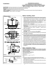
Installation
Figure 1
Dimensions
Before Installing Hood
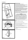
1. This hood is designed to be mounted flush to the rear wall (to
avoid clearance from wall to hood) and to the internal sides of
cabinet (where hood must be fixed); for this reason we
suggest installing this hood only inside a cabinet having an
internal width of 22
1
/
16
” for the 24” Model, 28
7
/
16
” for the 30” Model, 34
7
/
16
” for the
36” Model and with an internal depth of minimum 7
1
/
2
” . See figure 1.
The external depth of the cabinet must be minimum 10
13
/
16
” and
maximum 13
3
/
16
”. See figure 1.
Attention! Do not consider the door of the cabinet when
measuring.
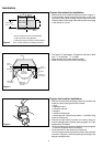
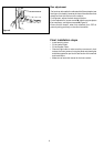
The appliance is also supplied with 4 spacers that can be
snapped at fixing point 1 and 2 , cabinets
1
/
4
” wider can be
used, see figure 2.
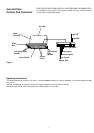
2. For the most efficient air flow exhaust, use a straight run or as few
elbows as possible.
CAUTION: Vent unit to outside of building ONLY.
3. If allowed in your area, use metallic flex ducting only to connect rigid
duct directly to transitions.
4. COLD WEATHER installations should have an additional backdraft
damper installed to minimize backward cold air flow and a nonmetallic
thermal break to minimize conduction of outside temperatures as
part of the ductwork. The damper should be on the cold air side of
the thermal break. The break should be as close as possible to
where the ducting enters the heated portion of the house.
A non-return smoke damper is supplied mounted on the transition.
5. Hood installation height above cooktop is at the users preference.
The lower the hood above the cooktop, the more efficient the
capturing of cooking odors, grease and smoke. We recommend that
the hood be installed 18” to 36” over an electric cooktop and 25” to
36” over a gas cooktop . Be sure that your hood model fits your
installation.
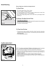
Basic Installation Steps
For easiest installation, the hood should be installed in the cabinet
before mounting the cabinet to the wall. In any case the installation
steps do not change.
Tools required for installation
Screw driver (philips # 1 )
Electric drill
with twist bit
5
/
64
” and
7
/
32
” or
15
/
64
”
Tape
This Hood can easily be installed following these basic steps:
• Prepare the cabinet (cut out bottom and top of the cabinet as
required and mark fixing points)
• Run conduit and duct sections to the hood and make connections
• Fix the hood to the cabinet
• Mount the cabinet on the wall
• Connect duct to the outside and conduit section to the service panel
FOR RESIDENTIAL USE ONLY
NOT TO BE INSTALLED OVER GAS GRILLS
PLEASE READ ENTIRE INSTRUCTIONS BEFORE PROCEEDING.
INSTALLATION MUST COMPLY WITH ALL LOCAL CODES.
IMPORTANT: Save these Instructions for the Local Electrical Inspector’s use.
INSTALLER: Please leave these Instructions with this unit for the owner.
OWNER: Please retain these instructions for future reference.
SAFETY WARNING: Turn off power circuit at the service entrance and lock out panel, before wiring this appliance.
REQUIREMENT: 120 V AC, 60 Hz. 15 or 20 Amp
Figure 2
24” - 30” - 36”