


IMPORTANT: Read Before Installing to Save Time, Work,-1 ’
assure proper performance, and owner’s warranty protection,
KD-IK INSTALLATION KIT
II An installation kit (KD-IK) for KitchenAid dishwashers is available from your local KitchenAid dealer. This kit
contains all parts and complete instructions needed for replacing almost any old dishwasher, or for a ne$
dishwasher installation.
-A
The KD-IK installation kit includes the following items:
Flexible Drain Hose, Copper Inlet Tubing, Double Compression Union, Double Com-
pression Elbow, Step-down Adapter, Strain Relief Bushing, Wire Nuts, and Hose Clamps.
CABINETRY
Opening for dishwasher should be 24” wide by
approximately 34-l/2” high. Remove all obstructions
at the upper rear of the opening-see Step 1 below.
ELECTRICAL SPECIFICATIONS
Voltage & Frequency -- 115 volts-60 hertz
Operating load
----- 13.5 amperes-KDS-18
7.9 amperes-KDC-18,
KDI-18 and
KDP-18
Maximum Fuse Size -- 15 amperes
Wiring must conform to local code and/or Nat.
Electrical Code.
PLUMBING SPECIFICATIONS
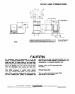
Plumbing must conform to local code. Use l/2” 0-D.
copper tube for water line. Dishwasher has 3/8” I.P.S.
internal thread at valve. A 90” compression ell
(furnished) should be used to connect tubing to valve.
Water flow pressure at dishwasher to be 20 PSI to
120 PSI. Water temperature at dishwasher should be
140” F. to 166” F. Drain size requires minimum 5/8”
O.D. copper tubing without air gap. Drain. line
requires min. g/16” I.D. copper tubing with air gap,
not furnished.
CAUTION:
Avoid getting joint compound inside
new joints. Hot water fill line must be flushed of
foreign matter before connection to dishwasher fill
valve. A hand shut off valve (not furnished) should be
located in an easily accessible area adjacent to the
dishwasher. ,_
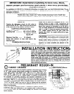
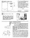
IN
ALLATION INSTRUCTIONa
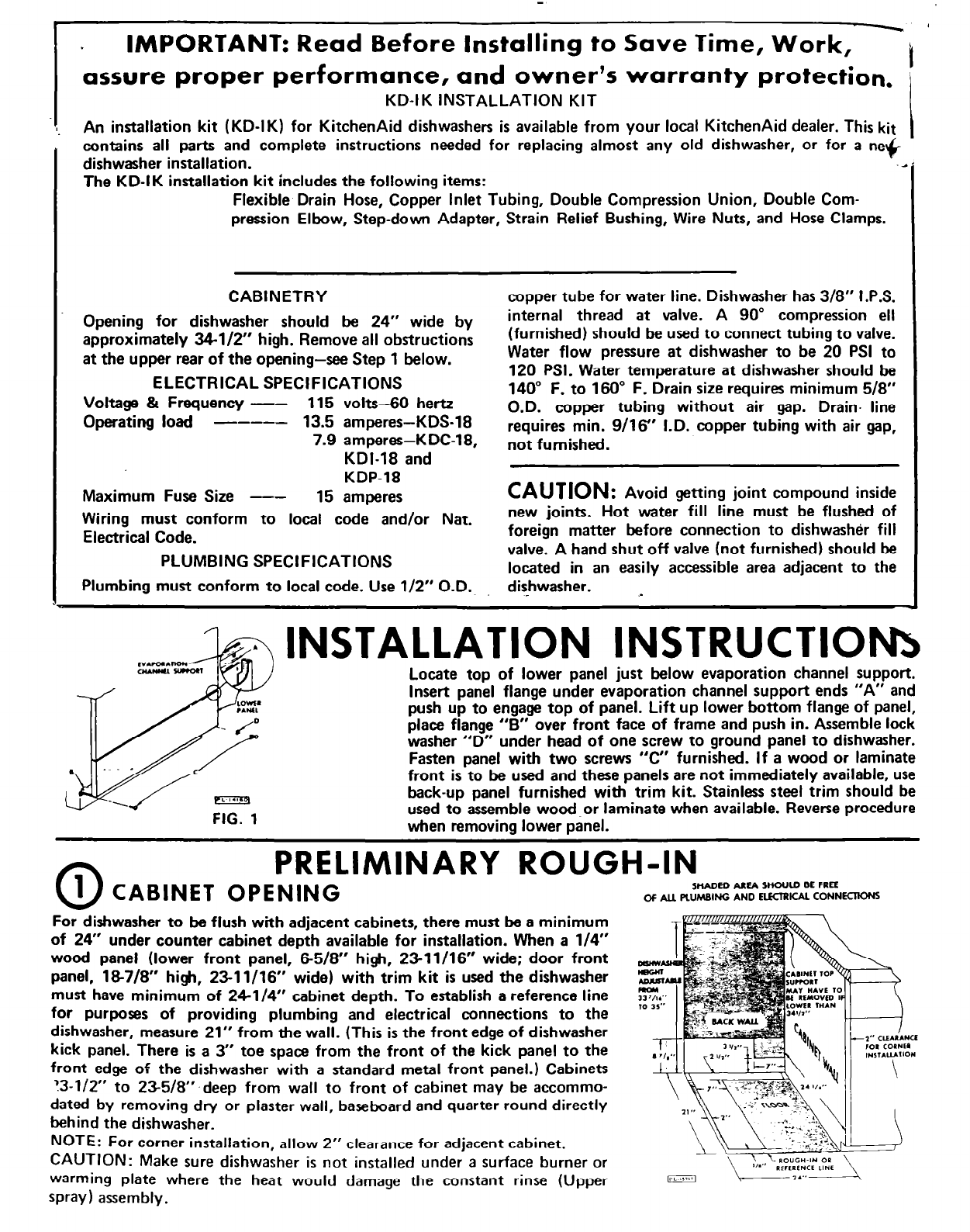
Locate top of lower panel just below evaporation channel support.
Insert panel flange under evaporation channel support ends “A” and
push up to engage top of panel. Lift up lower bottom flange of panel,
place flange “B” over front face of frame and push in. Assemble lock
washer “D” under head of one screw to ground panel to dishwasher.
Fasten panel with two screws
“C” furnished. If a wood or laminate
front is to be used and these panels are not immediately available, use
D
FIG. 1
back-up panel furnished with trim kit. Stainless steel trim should be
used to assemble woodor laminate when available. Reverse procedure
when removina lower oanel.
fl\
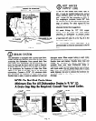
PRELIMINARY ROUGH-IN
u
1 CABINET OPENING
SHADED AREA WOULD BE FREE
OF AU FtUMBING AND ElECTRICAl CONNECTKMS
For dishwasher to be flush with adjacent cabinets, there must be a minimum
of 24” under counter cabinet depth available for installation. When a l/4”
wood panel (lower front panel, 65/8” high, 2311/16” wide; door front
panel, 187/8” high, 2311/16” wide) with trim kit is used the dishwasher
must have minimum of 24-l/4” cabinet depth. To establish a reference line
for purposes of providing plumbing and electrical connections to the
dishwasher, measure 21” from the wall. (This is the front edge of dishwasher
kick panel. There is a 3” toe space from the front of the kick panel to the
front edge of the dishwasher with a standard metal front panel.) Cabinets
13-112” to 235/8”‘deep from wall to front of cabinet may be accommo-
dated by removing dry or plaster wall, baseboard and quarter round directly
behind the dishwasher.
NOTE: For corner installation, allow 2” clearance for adjacent cabinet.
CAUTION: Make sure dishwasher is not installed under a surface burner or
warming plate where the heat would damage the constant rinse (Upper
spray) assembly.