


4-5
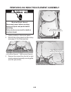
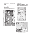
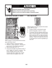
4. Disconnect the induction element assembly
connectors from the electronic board as
follows:
2-wire connector at CNT3.
2-wire connector at CNT1.
Red wire at FST1.
Green wire at FST2.
Induction element screw terminals at CNX1,
CNX2, CNX3 & CNX4.
FST2
CNT1
CNT3
CNX4
CNX3
CNX1
CNX2
5. Remove the induction element assembly
from the cooktop.
6. Unhook the two cover tabs and remove
the cover from the induction element you
are replacing.
Left Induction Element
Assembly Shown
LR Element
Cover & Tabs
LF Element
Cover & Tabs
Electronic Board
RF Element
Cover & Tabs
RR Element
Cover & Tabs
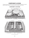
Left Induction Element Assembly
Right Induction Element Assembly
FST1