


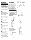
Electrical
requirements
Venting
requirements
Electrical ground is required on this
appliance.
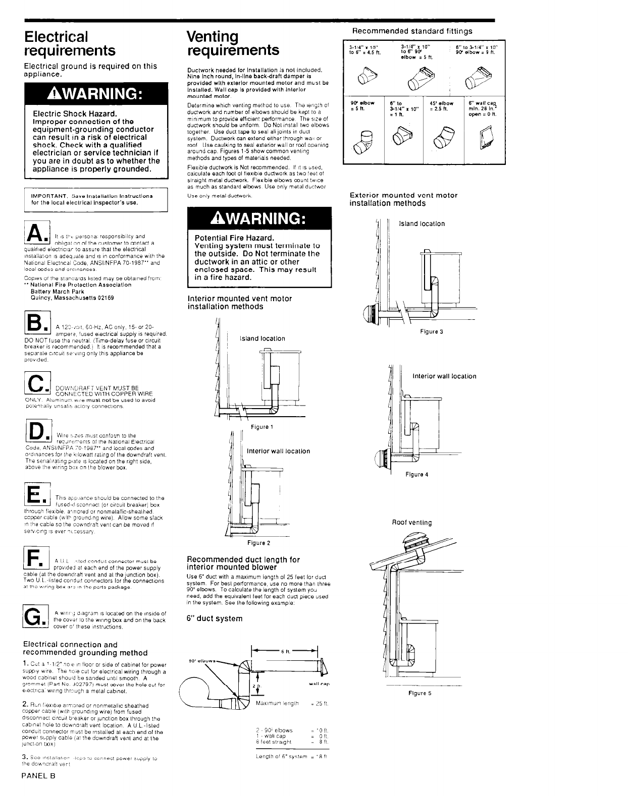
Recommended standard fittings
Ouchvork needed lor lnslallallon Is nol Included.
Nine Inch round, In-line backdraft damper Is
provided wllh exlerlor mounted motor and must be
Inslalled. Wall cap Is provided wllh lnlerlor
mounled motor.
Delermine which venl~ng melhod lo usa Thu leng:h 01
duclwork and number of elbows should be kept 10 a
mmmum lo provide efllcent perlormance The we of
duclwork should be undorm Do Nol inslall Iwo elbows
loqelher Use dud lake lo seal all ,o1n1s or. duel
Electric Shock Hazard.
Improper connection of the
equipment-grounding conductor
can result In a risk of electrical
shock. Check with a qualified
electrician or service technician if
you are in doubt as to whether the
appliance is properly grounded.
sykm Ductwork can extend elth& through wa’~ or
rod Use caulking to seal exierior wall or rcrot open\ng
around cap FIguris l-5 show common wwng
melhods and types of
malerials
needed
Flexible ductwork 1s Not recommended If I( 1s used,
calculale each fool 01 llexlble dudwork as Lwo feet of
slralghl metal ductwork. Flerlble elbows c~unl twce
as much as slandard elbows Use only melal dbclwor
Use onlv melal ductwork
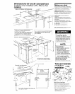
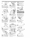
IMPORTANT: !;a,. lnstallallon lnsirucllons
Exterior mounted vent motor
installation methods
11 II
Island locallon
Potential Fire Hazard.
Venting system must terminate to
the outside. Do Not terminate the
ductwork in an attic or other
enclosed space. This may result
in a fire hazard.
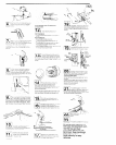
Interior mounted vent motor
installation methods
Island locallon
Figure 3
~nslallat~on IS adoq~ate and 1s in conformance wllh the
Nal~onal Eleclrlca, ‘Code. ANSIINFPA 70-1987” and
local mdes and or~!,nances
BaHery March Park
Cluincy, Massachussns 02169
IB
.
A 123 in,, 60 Hz, AC only, 15. or 20.
amper?. iused evxlr1c.3 supply 1s required.
DO NOT IUSB the ~leutral (Time-delay fuse or c1rcu0
breaker 1s recommended, II IS recommended thal a
separale c,rcui, se’v,ng oniy ,h,s appliance be
prov,ded
/c1
. DOW:;bHAFT VENT MUST BE
CONNECTED WITH COPPER WIRE
Code, ANSI/NFPA 70 ,987” and local codes and
o’dlwrces for Ihe k’lowa!, ral,ng 01 Ihe downdrall ye,,,.
The ser~al~ral~no o,aIe 1s located on Ihe riaht side.
lnlerior wall location
1
Flgure 4
1E
.
This +i, lance should be connecled lo the
lused-i! sconrecl (or circu,, breaker] box
Ibroug’l f;ex~ble, ar,nored or nonmelalllc-shealhed.
ccpper cable (wlb grouna ng we) Allow some slack
T Ihs cable so Ihe cowndrah vent can be moved II
sevclng is e”el nL:essar,
Roof venling
Figure 2
1F
A U L
.
ited cond”,, conneclor mus, be
prov,de> al each end 01 Ihs power supply
cable (al the downdran “en, and a, Ihe unct,on box)
Two U L ~+sled condu:! co,,,,eclors lor 1 e connenions
b
a’ I’le w~r,ng box ari in Ihe parls package
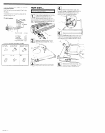
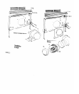
Recommended duct length for
interior mounted blower
Use 6’duct with a maximum lenglh 01 25 feet lo, dud
syslem For besl perlormance, use no more lhan three
90’ elbows. To calculale Ihe length 01 syslem you
need, add the eqwalenl Ieel for each duel piece used
in Ihe syslem. See Ihe lollowlng example
6” duct system
/G
A WIIII j d,agram ,s located on Ihe ,ns,de of
.
Ihe co”dr lo Ihe w,r,ng box and on Ihe back
cover o’ these ~mslrucl~ons
Electrical connection and
recommended grounding method
2. Rbn I~BXID,~ armored or nonme,allIc sheathed
copper cable (wllh grounding we) from fused
dlsconnecl c,rcu~l b,eaker or ,uncl,on box lhrauqh Ihe
cabInsI hole lo dounarall “en, local~on
A U L &led
cond”,t conr,eclor musl be ;nslalled a, each end of Ihe
cower supply cable ,a, :he downdraH venl and a, Ihe
,unc,.on tmxj
Figure 5
2 90. elbows
1 wali cap
8 !eel slra,gh,
Length o’ 6’syslem = ‘8 ,I
PANEL
B