


117
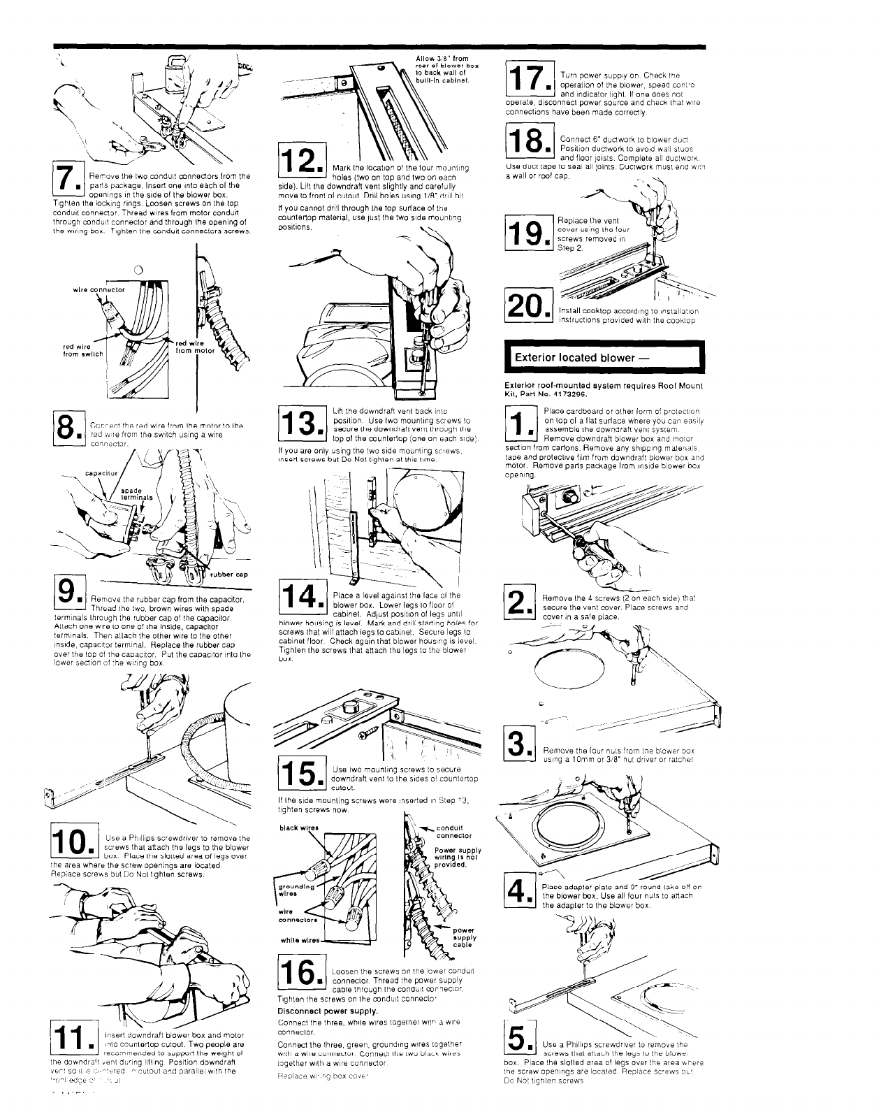
Turn pawer supp,y on Check ,,e
.
opera,,“” 01 Ihe blower, spead conl’”
and ndfcalor l,ghl If one doss no,
opeiale, disconnec! power source and checm lhal WIIB
connections have been made c”rred,y
(18
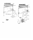
Conned 6’ dudwork lo blower due!
.
P”s111on ductwork lo avoid wal, s,u”s
and floor jousts Complele all duc!worK
Use duel lape to seal all ,“,nts Ductwork rnus, end WI!.,
a wall or rwf cap
-a
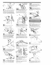
Rerove Ihe Iwo condull mnnectors lrom Ihe
holes (two on lop and two on each
side). Llfl the downdraft wnl sllghlly and carel~lly
move to Iron1 01 culout Drill holes “s,ng llB’dr,Il bit
n you cannot drill through Ihe top surface 01 ,hw
cnunlertop malerlal, us.8 JW Ihe two side mouwng
poSlll”“S
Tlghlen Ihe’l”&g r,ngs Loosen screws on Ihe lop
condull c”nnen”r Thread w,rws lrom motor conduit
through cnndult t”nneclor and through Ihe open,ng of
the wnng box Tlghlen Ihe cnndun c”nnecLors SC~QWS
3
l!-E!!l
. SC~QWS removed in
PJ!!L
l~S,r”~,~“ns pr”v,ded w,h the cooklop
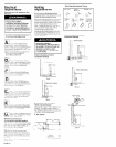
Exterior located blower -
I
Exlerlor roof-mounted syslem requires Roof Mounl
Kil, Part No. 4173296.
LIII Ihe downdrah “en, back I”,”
pxlll”” Use IWO mo”nllng SCIQWS lo
swcure Ihe downdrafl vwnl lhrough Ihe
lop01 Ihe munlertop (one on each sldo)
3
1
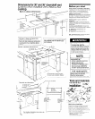
Place cardboard 01 olher form o’ prolec\‘“n
on lop 01 a llal surlace where you can easily
.
assemble Ihe downdrah vwnl syslem
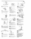
Remove downdrah blower box and molar
s@d~on from caflons Remove any shlpplng malw’ials
lape and proleclIve film from oowndrall blower box and
molar Remove pals package lrom inside blower wx
operxng,
H you are only us,ng Ihe Iwo side m”un,,ng s”ews
tnserl scrwws but Do Nol llghlen at IhIs l,me
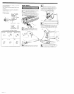
Remove Ihe 4 screws (2 on each side) tha!
swcurw Ihe “en, mver Place screws and
COYel in a safe place.
Thread Ihe
two, brown wires Wh spade
lermlnals lhrouah Ihe rubber ca” of the ca”acfloi
Allach one we-(” one of Ihe &de. cap&nor
leim~nals. Then allach the other we lo Ihe other
nstde, capacitor terminal. Replace Ihe rubber cap
over Ihe lop of Ihe caputor. Put Ihe capac,lor ,n,” Ihe
lower sed~on 01 .he w,~ng box
screws lhal w~ii attach legs lo cabinet.
Sew: legs IO
cabinet floor Check aga,n lhat blower houslrg IS level
Tighlen the screws ihal attach the legs l” the “lower
box
Remove the lour nbls from one b:oaer “ox
“s,ng a IOmm or 98’ nut dwer or ratchel
Use IWO mo”nll”g scrwws 10 Sec”1Q
downdrah vanI lo Ihe stdes 01 c”unler!“p
C”l”“l
If Ihe side mounting screws were inserted I” Step ‘3,
tIghten screws now
h
110
Use a PhIllIps screwdwer l” remove the
.
screws thal attach the legs l” Ihe blower
box Place the slolled area of legs over
the area where the screw opemngs are localed
Replace screfis bul Do No, llghlen screws
Place adapter plate
and 9’ ro’Jnd lake-on on
Ihe blower box. Use all four nuts lo attach
Ihe adapler lo Ihe blower box
116 1
Loosen Ibe screws
. connecloi Thread
on i,w lower condull
Ihe cave supply
l::sert downdraft blower box and mo,“,
I?!” counlenop cut”“, Two people are
recommended lo support Ihe welghlol
the aowndra’l ien; dkr,ng I’IIlng Posn~on downdrah
ibr’ so I, 8s ~,I.~“c’Qo
n ~u\o”I aid parallwl w,,h the
-
1 cable lhrough Ihe condull m~;lwcl”r
T\ghlen Ihe screws on Ihe mndult conneclo’
oisconnecl power supply.
Connec, Ihe Ihww. ,vh,le w,res iogelher wllh a W118
mnneclol
Use a PhIllIps screwdr
scrwws thal allach Ihe legs l” t
box Place Ihe slolled area 01 legs over Ihe area v.ri’re
the screw opemngs are localed Reolace sc’ews “1’
Do No! ,,ghlen screws