


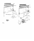

Wiring belween motor and blower box
iS not provided.
I I
supply mnnec,,on at llle lop
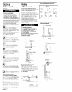
Wall Installations
. Use caulking compound belwee” mou”:,r”; ilar:-
and wall
Roof lnstallatlons
. Follow standard roof,“g procedures
The llashlng sheet should be Bnlered over 1’1s
oper.~“g I” Ihe roof
The lower edge o: Ihe flash’ng should IIB on lop ‘oi
tile shingles and Ihe upper edge should be
uldernealh Ihe sh,ng,es
Seal Ihe assembly belwee” rhe rool la” a?d lla 71”;
KII~ rooltng mask lo prevenl ieaks
m
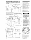
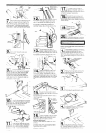
Lilt 11,~ asn~drsll van, back ,“,o pos,,,o?
Use !WL mo”n!,“g screws lo seclire Ihe
.
downcra!r “en, through the Iop 01 Ihe
counlerlop (one on each side) If you are
only “song Ihe t&o s,de mou”:,“g screws, wsel? sc:ews
But Do Nol ughlen a, Ims t,me
El
Place a level aga,“st Ihe lace 01 Ihe blower
, box Lswer legs 10 lloor of cablnet Adjust
pos~!~o” oi legs ~“111 blower housing 18 level
Mark and drill s,all,“g holes for screws lhat VIII auach
legs lo cabInal Secure legs lo cablnel lloor Check
aga~n lhat blower housing 1s level Tlghle” Ihe screws
lhat aitach the lqs lo Ihe blower box
D!i
. Lse lMi0 moLnl,ng screws ;o secure
cowndran “en! to ,ne sides 01
counterlop c”:wI If the side moun,,“g screws v,ere
lKse”*o 11 S!ep 8 !Igh!er screws now
ml
Uelemne the localion where Ihe
dx~erior blower assembly ~111 be
.
nslalled Cul a 10’ diameter hole
1 !he wall or roe,
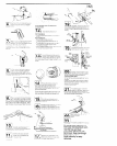
PANEL E
connector. Thread wares lrom motor
conduil lhrough condull connector and lhrough !he
o~en~“q of Ihe WI~I”~ box Tlahte” Ihe conduit
Co”“BctOl screws lo-secure the condull lo Ihe blovier
houslng
Connect Ihe red we lrom the mo!or 10
Ihe red wre from !he switch us,“g a
113
.
Connect 9’ ouctwork 10 blower due
PoWon ductwork ,o avo,d wall slrds
and lloor jo1s1s Complele all ductwork.
Use duct tape lo seal all ,o~“ls Ven~cal
ductwork lor wall mounled ~nslallal,ons should p,,ch
down sl~ghlly loward the venl lo allow mo~sl”~ lo run lo
ouls,de
,
;/-
“\,-;
Q
r 7
/14
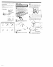
Remove Ihe dome lop Loose” Ihe
, ~,‘a,” relic1 screws Thread Ihe
molar w,nng through the strain
reltel. Tlghlen Ihe screws on the slra” rel~el
Conneci Ihe while and black w,res 01 Ihe motor n’:,“g
cable lo Ihe while and black leads of Ihe motor wI,h
IWIS-on wre mnneclors.
Connect Ihe green. grounding wire of Ihe motor w r,ng
cable lo Ihe grounding connecl~o” sc,ew Place w,res
under clip lo preven, hilling Ihs motor cooling b,aee
Run motor wlnng lhrough Ine dLc.1
access area lo the w,r,“g box on !ye
blower box
For wall-mounted installations, rep ace the
dome top lo cover Ihe molar and
mnne*,ons. Roof lnslallallons requ,re a
roof cap lo be used I” place 01 Ihe come
El
Remove tile wlr,“g box cover screw
. Place co”er and screw I” a safe zlace
Pull ,wres tlrough ope”,rg
I -I
120
Loose” Ihe screws on ,he lower conad,,
. conneclor Thread Ihe power suppiy
cable through Ihe condull mnneclor
Tlghlen the screws on Ihe condull co”“exor
Disconnect power
supply.
Conned the lhree, while w,res logelher w,,h a w,re
conneclol
Connect Ihe three, green, grou”d,“g w,res logelher
wllh a w!re connector Connect Ihe IWO t,lacn w,:es
together wllh a w\re connector
Replace wlrlng box cower
j211
Turn power supply on Cleck the
. operal~on of Ihe blower, bpeed conlro:
and lndlcalor llghl ti one does not
opsrale, dlswnnecl power source and check lhal w,re
mnnecl~on~ have bee” made cone+.
COYal “sing
e four
screws removed I”
Instail cooklop arxord~na 13 ,“s,a!Ie’,zn
~“slr~cl~ons prov,ded WI h :he co&o;,
To get the most efficient use
from your new downdraft vent,
read
the Use and Care
Information section on the
back
cover. Keep Installation
Instructions and Use and Care
Guide close by for easy
reference.