


5
Electrical requirements
Installation steps
Important: Observe all governing
codes and ordinances.
It is the customer’s responsibility:
•To contact a qualified electrical
installer.
•To assure that the electrical
installation is adequate and in
conformance with National
Electrical Code, ANSI/NFPA 70
— latest edition*, or CSA
Standards C22.1-94, Canadian
Electrical Code, Part 1 and
C22.2 No.0-M91 - latest
edition** and all local codes
and ordinances.
If codes permit and a separate
ground wire is used, it is
recommended that a qualified
electrician determine that the
ground path is adequate.
A 120-volt, 60-Hz, AC-only, fused
electrical system is required on a
The range hood must be
connected with copper wire only.
The range hood should be
connected directly to the fused
disconnect (or circuit breaker) box
through flexible armored or
nonmetallic sheathed copper cable. A
U.L.- or C.S.A.-listed strain relief must
be provided at each end of the power
supply cable. Wire sizes (COPPER
separate 15-amp circuit, fused on
both sides of the line.
Do not ground to a gas pipe.
Check with a qualified electrician
if you are not sure range hood is
properly grounded.
Do not have a fuse in the neutral
or ground circuit.
IMPORTANT:
Save Installation Instructions for
electrical inspector’s use.
WIRE ONLY) and connections must
conform with the rating of the
appliance as specified on the
model/serial rating plate.
Wire sizes must conform to the
requirements of the National Electrical
Code ANSI/NFPA 70 — latest edition*,
or CSA Standards C22.1-94, Canadian
Electrical Code Part 1 and C22.2 No.
0-M91 - latest edition** and all local
codes and ordinances.
A U.L.- or C.S.A.-listed conduit
connector must be provided at each
end of the power supply cable (at the
range hood and at the junction box).
Copies of the standards listed may be
obtained from:
* National Fire Protection Association
Batterymarch Park
Quincy, Massachusetts 02269
** CSA International
8501 East Pleasant Valley Road
Cleveland, Ohio 44131-5575
Do not cut a joist or stud unless
absolutely necessary. If a joist or stud
must be cut, then a supporting frame
must be constructed.
Before making cutouts, make sure
there is proper clearance within the
ceiling or wall for exhaust vent.
1. If possible, disconnect and move
freestanding or slide-in range from
cabinet opening to provide easier
access to rear wall. Otherwise put a
thick, protective covering over
countertop, cooktop or range to protect
from damage or dirt. Select a flat
surface for assembling the unit. Cover
that surface with a protective covering
and place all canopy hood parts and
hardware in it.
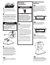
2. Determine and mark the
centerline on the wall where the canopy
hood will be installed.
3. Attach the lower bracket securely
to the wall at the height shown. The
dimension shown on page 3 is for
mounting the canopy hood 24” (61 cm)
above cooking surface. The lower
bracket must be mounted with the
Preparation
flanges on the bottom of the bracket so
that the canopy hood will hang from
them.
If a backsplash is to be used with this
canopy hood, it MUST be installed
before the canopy hood. Installation
instructions for the backsplash are
supplied with the backsplash kit. The
height of the backsplash will determine
the height of the bottom edge of the
canopy hood.
4. Attach the middle and upper
brackets securely to the wall. The upper
bracket should be installed about 1/8”
(3 mm) away from the ceiling. The
middle bracket (bright metal) must be
installed with ends touching the wall
and the curves facing outward.
Note: If the canopy hood is installed
more than 24" (61 cm), the middle
bracket must be installed at the bottom
point of the upper chimney sleeve.
It may be necessary to cut the upper
chimney. Be careful not to damage or
bend upper chimney when cutting.
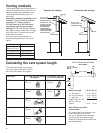
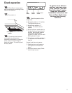
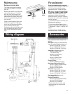
5. Determine and make all
necessary cuts in the wall for the vent
system. Install the vent system before
the canopy hood. See venting methods
on page 4.
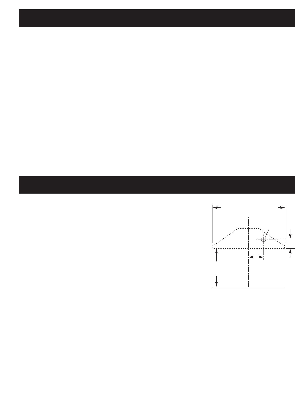
6. Determine the required height
for the power supply cable and cut a
1-1/4" (3.2 cm) hole at this location.
Run wire through hole according the
National Electrical Code or CSA
Standards and local codes and
ordinances. There must be enough
power supply cable from the fused
disconnect (or circuit breaker) box to
make the connection in the hood’s
electrical box.
Use caulking to seal all openings.
Do Not turn on power until
installation is completed.
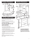
24
"
(61.0 cm) min.
base cabinet or
cooking surface
7-3/4
"
(19.7 cm)
4-7/16
"
(11.3 cm)
30" hood 29-15/16" (76 cm)
36" hood 35-7/8" (89.9 cm)
48" hood 47-1/4" (120 cm)
1-1/4
"
(31.8 mm)
dia. hole