


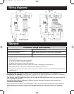

Electrical requirements
Installation steps
Important: Observe all governing
codes and ordinances.
It is the customer’s responsibility:
•To contact a qualified electrical
installer.
•To assure that the electrical
installation is adequate and in
conformance with National
Electrical Code, ANSI/NFPA 70
— latest edition*, or CSA
Standards C22.1-94, Canadian
Electrical Code, Part 1 and
C22.2 No.0-M91 - latest
edition** and all local codes
and ordinances.
If codes permit and a separate
ground wire is used, it is
recommended that a qualified
electrician determine that the
ground path is adequate.
A 120-volt, 60-Hz, AC-only, fused
electrical system is required on a
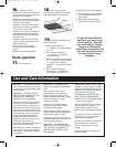
The range hood must be connected
with copper wire only.
The range hood should be
connected directly to the fused
disconnect (or circuit breaker) box
through flexible armored or
nonmetallic sheathed copper cable.
A U.L.- or C.S.A.-listed strain relief
must be provided at each end of the
power supply cable. Wire sizes
separate 15-amp circuit, fused on
both sides of the line.
Do not ground to a gas pipe.
Check with a qualified electrician if
you are not sure range hood is
properly grounded.
Do not have a fuse in the neutral or
ground circuit.
IMPORTANT:
Save Installation Instructions for
electrical inspector’s use.
(COPPER WIRE ONLY) and
connections must conform with the
rating of the appliance as specified
on the model/serial rating plate.
Wire sizes must conform to the
requirements of the National
Electrical Code ANSI/NFPA 70 —
latest edition*, or CSA Standards
C22.1-94, Canadian Electrical Code
Part 1 and C22.2 No. 0-M91 - latest
edition** and all local codes and
ordinances.
A U.L.- or C.S.A.-listed conduit
connector must be provided at each
end of the power supply cable (at the
range hood and at the junction box).
Copies of the standards listed may be
obtained from:
* National Fire Protection Association
One Batterymarch Park
Quincy, Massachusetts 02269
** CSA International
8501 East Pleasant Valley Road
Cleveland, Ohio 44131-5575
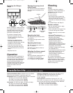
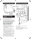
It is recommended that the vent system be installed
before hood is installed.
Do not cut a joist or stud unless absolutely necessary. If a
joist or stud must be cut, then a supporting frame must
be constructed.
Before making cutouts, make sure there is proper
clearance within the ceiling or wall for exhaust vent.
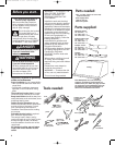
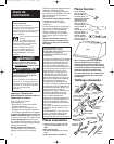
Check that all the installation parts and the box with
filters have been removed from the shipping carton.
1. If possible, disconnect and move freestanding or
slide-in range from cabinet opening to provide easier
access to rear wall. Otherwise put a thick, protective
covering over countertop, cooktop or range to protect
from damage or dirt. Select a flat surface for assembling
the unit. Cover that surface with a protective covering and
place all hood parts and hardware in it.
2.Determine and mark the centerline on the wall
where the hood will be installed. If the vent system is
already installed, use centerline of vent opening.
3.If venting horizontally out the back of hood and vent
system is not installed, mark and cut vent opening now.
4.
Important: If used, Backsplash Kit must be
installed before installing the hood.
If a backsplash is not used, go to Step 5.
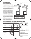
Backsplash installation: (The hardware package
supplied with the kit includes 4 plastic wall anchors
and mounting screws.)
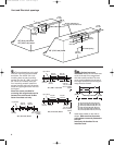
• The height of the backsplash will determine the height
Preparation
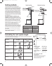
Extends from
19-23/32" (50.1 cm)
to 39" (99.1 cm)
3/8" (9.5 mm)
top of backsplash
corner
mounting
hole (4)
1" (25.4 mm)
36" (91.4 cm)
42" (106.7 cm)
48" (121.9 cm)
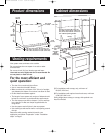
of the hood. Note: The minimum height of the hood
above the cooktop, as shown on Page 3, is 30"
(76.2 cm). The backsplash can be extended from
19-23/32" (50.1 cm) to 39" (99.1 cm). Note: As the 30"
(76.2 cm) installation height increases, the hood's
capture area decreases.
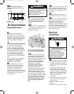
• Determine the height of the hood.
• Position the hood on the wall so that the top of the
backsplash is at the height of the bottom edge of
hood. Mark the location of the four corner holes. It is
recommended that the backsplash be attached to the
wall at all four corners. However, the lower flange
can be secured between the wall and backsplash,
countertop or cabinet base without using the bottom
corner screws.
• Drill 5/16" (8 mm) holes.
• Push the plastic wall anchors all the way into the holes.
• Position the holes in the backsplash over the wall
anchors and attach using the screws supplied.
5
YL10564/8284829B 8/7/01 3:32 PM Page 5