


HP-4
SECTION 3
Blender OVERVIEW
(Refer to Figures 1 and 2)
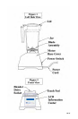
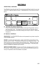
3.1 BLENDER MOTOR
• Motor Cover: Houses the power unit in a durable, easy-to-clean
polycarbonate.
• Touch Pad: Consists of six buttons that contain pre-programmed settings for
selective blender control, a pulse button, and two speed control buttons.
• LCD Information Center: will indicate status of unit as well as overload or
over-temperature conditions.
• Power Unit: This unit is located within the blender motor and contains the
machinery that runs the blender.
• Power Switch: Located on the back lower-right corner of the power unit.
3.2 BLENDER JAR ASSEMBLY
The blender jar assembly consists of the blender jar, blade assembly, and lid.
• Jar: Made from polycarbonate to provide maximum efciency and clear
visibility of blender performance.
• Blade Assembly: Stainless steel designed to provide fast consistent blending
SECTION 4
INSTALLATION
We recommend that surge protection be placed between the receptacle and the
blender motor.
1. Place blender on a at, clean and dry surface.
2. Make sure a plug outlet is available within four feet of the blender motor.
3. Ensure that the unit is turned off before plugging it into a separate 120-volt
receptacle.
4. Ensure that blender vents are unobstructed to allow proper cooling during
use.