


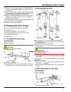
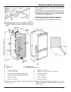
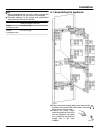
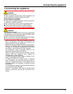
For appliances with a fixed water supply for the
IceMaker:*
u
Connect the IceMaker as indicated the section entitled
Water Supply.*
u
Fit the locking clip
Fig. 11 (62)
.*
Fig. 11
*
All appliances:
u
Push the appliance 3/4 of the way into the recess.
u
Remove the covers
Fig. 9 (5,6,7)
.
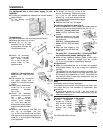
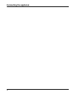
u
Screw
Fig. 12 (61)
the
equalizer trim
Fig. 12 (20)
to
the appliance through the
oblong holes on top.
Fig. 12
u
Fasten all mounting
brackets
Fig. 13 (34)
with
hex head screws
Fig. 13 (35)
to the pre-
bored holes in the
appliance door.
Fig. 13
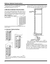
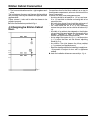
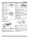
With 5/8 '' (16 mm) thick unit
walls = 22-3/8 '' (568 mm) wide
recess:
u
Clip a spacer
Fig. 14 (23)
onto
the upper hinges and a
spacer
Fig. 9 (24)
onto the lower
hinges.
Fig. 14
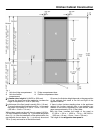
u
Attach the top and bottom
covers
Fig. 15 (53)
to the
mounting brackets
Fig. 15 (50)
.
u
Fasten the mounting
brackets
Fig. 15 (50)
at the
top with screws
Fig. 15 (55)
and at the
bottom with screws
Fig. 9 (51)
such that the
bracket can still be moved
slightly to the left and to the
right.
Fig. 15
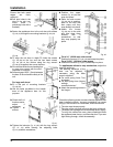
u
Remove the protective film from the
trim
Fig. 16 (22)
.Attach the trim
Fig. 16 (22)
on the handle side and flush
with the front to the projecting edge of the
cover
Fig. 15 (53)
and glue to the sidewall
of the appliance.
Fig. 16
u
To shorten the trim
Fig. 16 (22)
at the
bottom, if necessary: Position the cover
Fig. 9 (54)
on the bottom mounting
bracket
Fig. 15 (50)
and shorten the trim
Fig. 16 (22)
so that it is flush with the upper
edge of the cover.
u
Remove the cover
Fig. 9 (54)
again.
To slide the appliance in and align it:
u
Slide the appliance in until it comes into contact with the
covers
Fig. 15 (53)
on the side wall of the unit.
Fig. 15
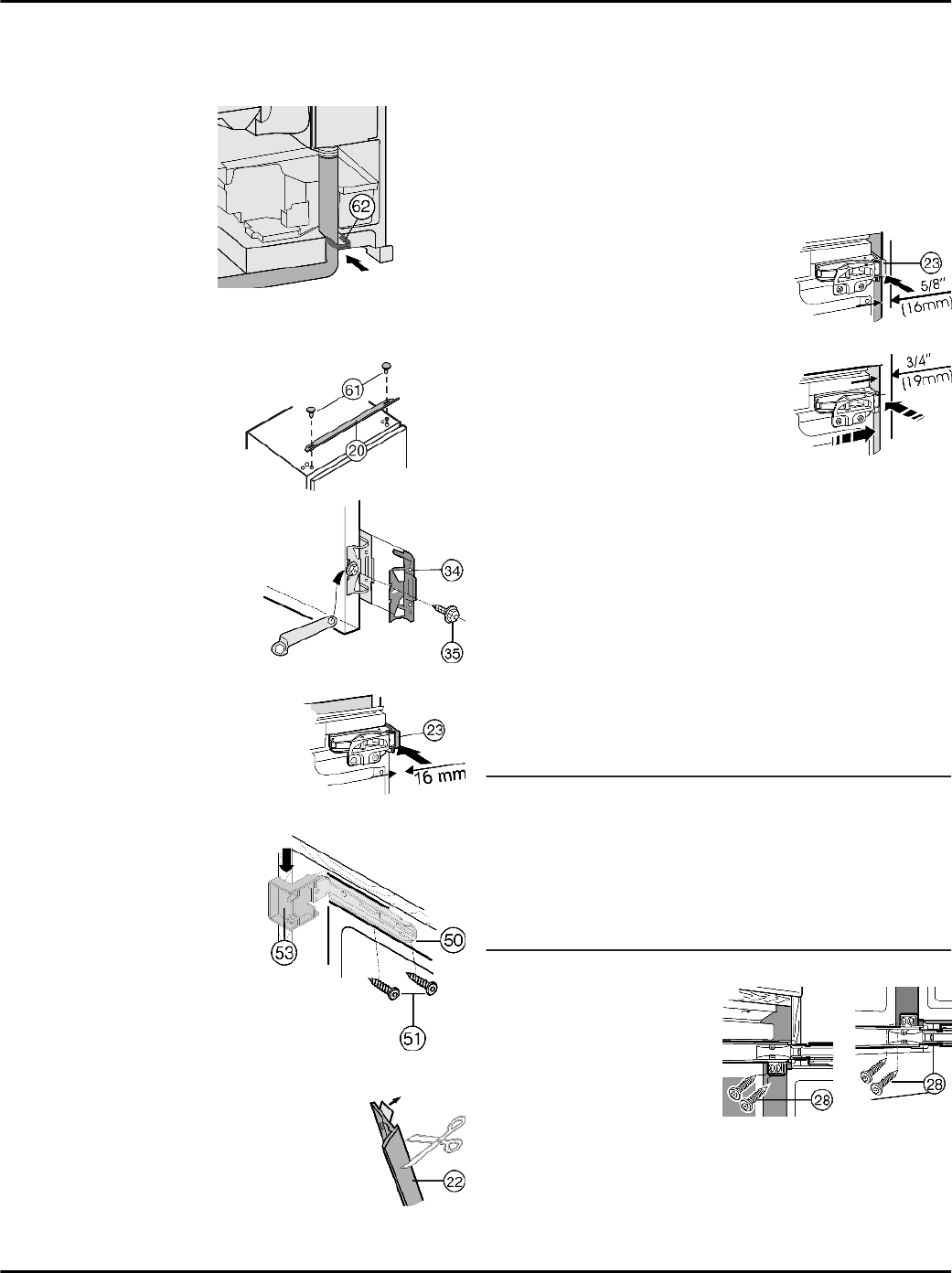
With 5/8 '' (16 mm) thick unit
walls = 22-3/8 '' (568 mm) wide
recess:
u
Allow the spacers on the side
wall of the unit to butt up against
the appliance.
Fig. 17
With 3/4 '' (19 mm) thick unit
walls = 22-1/8 '' (562 mm) wide
recess:
u
Align the front edges of the
hinges flush with the side wall
of the unit.
Fig. 18
For units (5/8 '' (16 mm) and 3/4 '' (19 mm)) with door
stop components (knobs, sealing lips, etc.):
u
Allow for the additional distance (depth of door stop
components). Allow the hinges and the covers
Fig. 15 (53)
to protrude by the additional distance.
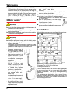
All appliances:
u
Adjust the adjustable feet
Fig. 9 (25)
with the supplied
open-ended wrench
Fig. 9 (26)
to align the appliance
vertically.
w
The appliance is now correctly positioned in depth. The
gap between the front edge of the side wall of the unit
and the body of the appliance is 1-21/32 '' (42 mm) all the
way around. (Allow for door stop components, such as
knobs and sealing lips.)
Note
Malfunction due to incorrect assembly!
If the spacing is not correct, the door may not close. This
can cause icing up, the formation of condensate, and
malfunctions.
u
A continuous space of 1-21/32 '' (42 mm) must be
maintained. (Allow for door stop components, such as
knobs and sealing lips.)
To secure the appliance in the recess:
u
Screw chipboard
screws
Fig. 19 (28)
on
both doors at the top
and at the bottom
through the hinge
plates.
Fig. 19
On the handle side at the top:
Installation
10