


20 CN/CNa..3
- Suspend lower door, close.
- Rotate hinge component
4by 180°, remove hinge pin 5,
turn by 180° and replace. Mount both parts in the hinge
bq:
slide the pin into the door mounting through the hinge, tilt
in the hinge component, slide up and attach with screw
3.
W Align the door
flush
with the body of the appliance using
the slot on the hinge
bq, then tighten screw 3.
W Attach the plinth panel
1and click into place by pressing.
W With the door open, insert the cover
2 in the plinth panel
at the front and click into place at the back.
W Transfer* door handles
br and plugs bt. With the door
open, carefully lift out the pressure plates*
bs at the front
and slide away; unscrew handle using a Torx® or Phillips
screwdriver*.
Reassemble in reverse order: replace the pressure plates
and click into position.
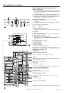
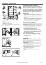
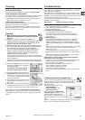
Insertion into row of kitchen units
Fig. U. The appliance can be integrated into the kitchen units.
To adapt the appliance to the height of the row of kitchen
units, a suitable top cupboard can be fitted above the
appliance
1.
For ventilation and air extraction, an exhaust air shaft at least
50 mm deep must be provided on the rear of the top cupboard
over the entire width of the cupboard. The ventilation cross-
section below the ceiling of the room should be at least 300 cm
2
.
Generally, the bigger the cross section, the more economically
the appliance operates.
W When integrating with standard kitchen units (depth max.
580 mm) and decor panels of up to max. 2 mm thick, the
appliance can be installed directly next to the kitchen unit.
The door of the appliance protrudes beyond the front of the
kitchen unit 34 mm at the side and 51 mm in the centre of
the appliance. This allows it to be opened and closed
easily.
W When installing the appliance next to a wall
4, a distance
on the hinge side of min. 36 mm is required between the
appliance and the wall (handle projection with door open).
1Top cupboard 3 Wall of kitchen units
2Refrigerator/freezer 4 Wall
Note on fitting decor panel*
(with white appliances of height H = 1806 and 1982 mm)
With decor panel and decor frame, you can adapt the appli-
ance to the front of the kitchen units or contrast with them.
The decor panels can be obtained from your kitchen furniture
supplier. The decor frames can be retrofitted from your kitchen
furniture supplier.
If you wish to fit the decor panel yourself, you require a drill or
cordless screwdriver to pre-drill the retaining holes. The door
handles are to be replaced by the rigid handles included in
the decor frame retrofit set. For further assembly instructions
and dimensions, please see the assembly instructions
included in the retrofit set.
___________________________________________________
The manufacturer is continually working on the continous
improvement of all types and models. We therefore hope for
your understanding that we reserve the right to alter design,
equipment and technology without notice.
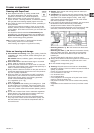
Instructions for installation and modification
For the external dimensions of the appliance, see fig. S
attached to the rear of the appliance and the table below.
Appliance, gross capacity of models (l) Height H
see type plate (mm)
289 (30..) 1625
337 (35..) 1806
375 (39..) 2000
383 (40..) 1982
Installation instructions
Do not install the appliance side-by-side with another refrige-
rator or freezer. This is important to prevent condensation and
consequential damage from it.
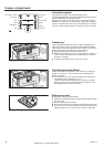
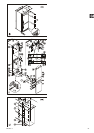
Changing over door hinges
Fig. T. The door hinges can be changed from one side to the
other if required:
Only change over door hinges when mains plug is discon-
nected!
W With the door open, lever out plinth panel 1 on the hinge
side with a screwdriver and remove from front.
- Lever out cover 2 with a screwdriver. Close door.
- Unscrew screw M5
3.
W Pull hinge component
4 with hinge pin 5 out from under-
neath and remove.
- Open door, lift out at bottom and remove.
- Pull middle hinge pin
6out from underneath.
- Tilt out top door and lift off from underneath (with version
I,
do not lose spacer sleeve
9).
W Transfer all hinge components onto the other side:
W Top: depending on version, proceed as follows:
Version I (
visible
operating panel): Lever out covers 8with a
screwdriver
at the front and remove at an angle from below.
Remove hinge pin 7 and insert on the opposite side. Use
the hexagon socket on the open-ended spanner provided
(spanner width 5).
Fit covers 8 again: insert at rear and click
into place at front.
Version II (
concealed
operating panel): Lift up cover 8 on
handle side, push outwards; lift up cover on hinge side and
pull off.
- Unscrew earthing plate
cm: first earthing screw cl, then inner
retaining screw
cq.
- Unscrew hinge
9: first undo earthing screw cl, then retai-
ning screws
cq. Fit hinge 9to opposite side: for easy assem-
bly, fit hinge from above and first tighten with the upper retai-
ning screw
cq M5, then screw cq and finally earthing screw
cl M4.
-
Turn earthing plate cm through 180° and screw tight again
on
the new handle side: first retaining screw cq, then earthing
screw
cl.
- Insert hinge pin
7 in the other retaining hole. Use the
hexagon socket on the open-ended spanner provided
(spanner width 5).
- Fit covers
8 again: insert hinge-side cover by sliding out-
wards and click into position; insert handle-side cover by
sliding inwards and click into position.
W Centre: Change over cover
bl with hinge bm: unscrew screws,
lift off cover
bl and hinge bm to the side, turn through 180°
and replace on the other side, remove hinge bushing
bn and
re-insert from top.
- Bottom: Using a screwdriver, remove the spacer
bo, fig. T1,
and replace on the other side.
W Re-attach the doors:
- Remove plugs
bp from the door mounting points and re-
place on the other side.
- Suspend top door in hinge pin
7(with version I, do not
lose spacer sleeve 9), close door.
- Slide middle hinge pin
6 into the door mounting from
below through the hinge
bm. Make sure the door is flush
with the body of the appliance; adjust if necessary using
the slots on the hinge.
* depending on model and options