


Impinger II – Advantage Digital Express Service Manual - Domestic
21
CAPACITOR – REPLACEMENT
A. Shut off power at main breaker.
B. Remove rear control box cover.
C. Discharge capacitor.
D. Remove capacitor.
E. Reassemble in reverse order and check system operation.
ON/OFF SWITCH – REPLACEMENT
A. Shut off power at main breaker.
B. Remove conveyor and front control box cover.
C. Depress spring clips on sides of switch and push out.
D. Remove wires from switch and mark for reassembly.
E. Reassemble in reverse order and check system operation.
NOTE: Make sure switch housing is fully seated in control box housing.
FUSE HOLDER – REPLACEMENT
A. Shut off power at main breaker.
B. Remove rear control box cover.
C. Remove wires from fuse holder and mark for reassembly.
D. Remove mounting screws or mounting nut on fuse holder and remove fuse holder.
E. Reassemble in reverse order and check system operation.
COOLING FAN, CONTROL BOX – REPLACEMENT
A. Shut off power at main breaker.
B. Remove appropriate control box cover and conveyor if necessary.
C. Remove four mounting screws from fan frame.
D. Disconnect power cord and remove fan.
E. Reassemble in reverse order and check system operation. Check for air flow.
THERMOSTAT, COOLING FAN, REPLACEMENT
A. Shut off power at main breaker.
B. Remove conveyor and front control box cover.
C. Remove wires and mark for reassembly.
D. Remove two mounting screws and remove thermostat.
E. Reassemble in reverse order and check system operation.
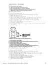
BURNER BLOWER MOTOR – REPLACEMENT
A. Shut off power at main breaker.
B. Remove rear control box cover.
C. Unplug motor connector.
D. Remove three mounting screws from blower tube at burner housing.
E. Remove air shutter assembly from old motor for assembly on new motor.
F. Reassemble in reverse order and check system operation.
NOTE: Check air shutter at approximately ½ open and adjust to get a blue flame with an occasional
tip of yellow under high flame. A view port in the burner assembly should be used to observe flame.
HI-LIMIT THERMOSTAT, OVEN CAVITY – REPLACEMENT
A. Shut off power at main breaker.
B. Remove conveyor and bottom finger assembly. Remove rear control box cover.
C. Remove capillary bulb from bracket in oven chamber and pull capillary tube through tube into
control box.
D. Remove all wires and mark for reassembly.
E. Remove mounting nut and remove thermostat.