


Impinger II – Advantage Digital Express Service Manual - Domestic
24
BYPASS ORIFICE – REPLACEMENT
A. Shut off power at main breaker.
B. Shut off gas supply to the oven and disconnect the flexible gas line to oven.
C. Remove rear control box cover.
D. Disconnect bypass tube from gas valve.
E. Remove bypass orifice from gas valve.
F. Reassemble in reverse order and check system operation.
G. Check all gas line fittings for leaks.
MAIN BURNER ORIFICE – REPLACEMENT
A. Shut off power at main breaker.
B. Shut off gas supply to the oven and disconnect the flexible gas line to oven.
C. Remove rear control box cover.
D. Remove burner manifold. See “TEMPERATURE REGULATION VALVE”.
E. Remove main burner orifice from burner manifold.
F. Reassemble in reverse order and check system operation.
G. Check all gas line fittings for leaks.
REVERSING SWITCH – REPLACEMENT
A. Shut off power at main breaker.
B. Remove rear control box cover.
C. Remove wires from reversing switch and mark for reassembly.
D. Remove mounting nut and remove switch.
E. Reassemble in reverse order and check system operation.
CONVEYOR DRIVE MOTOR – REPLACEMENT
A. Shut off power at main breaker.
B. Remove conveyor and both control box covers.
C. Disconnect all wiring from motor and mark for reassembly.
D. Remove coupling from motor drive shaft.
E. Remove four screws and remove conveyor motor and mounting bracket.
F. Remove mounting bracket from conveyor motor.
G. Reassemble in reverse order and check system operation.
REVERSING CONVEYOR DIRECTION
A. Shut off power at oven switch.
B. Set conveyor reversing switch in the other position.
C. Turn oven “on” and check for proper operation.
CAPACITOR, CONVEYOR DRIVE MOTOR – REPLACEMENT
A. Shut off power at main breaker.
B. Remove rear control box cover.
C. Discharge capacitor before removing wires. Mark wires for reassembly.
D. Remove mounting screw and remove capacitor.
E. Reassemble in reverse order and check system operation.
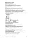
AIR PRESSURE SWITCH – REPLACEMENT
A. Shut off power at main breaker.
B. Remove conveyor and front control box cover.
C. Disconnect wiring from air pressure switch and mark for reassembly.
D. Disconnect air tube from air pressure switch.
E. Remove two mounting screws and remove air pressure switch.
F. Reassemble in reverse order and check system operation. Be sure to calibrate new air pressure
switch. For proper calibration, see below.