


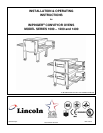
Impinger I – 1000 Series Ops Manual
9
UNLOADING
When the oven arrives it should consist of:
1. A crate containing oven body, conveyor, fingers, crumb pans, and pan stops. (Some models may have
the conveyor packed separately.)
2. A package containing the stand and top.
It is recommended that you have a material-handling device available to unload.
DO NOT LIFT EXCESSIVE WEIGHT!
IF THERE IS APPARENT DAMAGE:
UNITED STATES AND CANADA: Arrangements should be made to file a claim against the carrier, as Interstate
Commerce Regulations require that the consignee initiate a claim.
ALL SHIPMENTS TO OTHER COUTRIES: Freight terms will be developed and extended on an individual basis.
Proper and secure storage facilities should be arranged for the oven(s). If necessary, protect it from outdoor or
damp conditions at all times before installation.
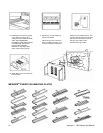
UNCRATING
When you have all the crates unloaded, open the crates and remove the plastic covers. Inspect at once for
concealed damage. If anything appears to be damaged, contact the appropriate persons immediately to file a
damage claim. After completing this inspection, finish unpacking the oven and all other components. Be sure to
remove the cardboard from the plenum shroud. Move all components inside near the area where they will be
assembled in the order in which they will be assembled.
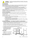
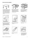
THE OVEN WILL CLEAR THROUGH A 30” (762 mm) DOORWAY BY USING THE FOLLOWING PROCEDURE:
1. Model 1000 and 1400 Series
A. Remove conveyor; see page 16 for instructions. (Some units may have conveyor packed separately.)
B. Remove thumb screws and baffle from the left side of the oven.
C. Place the left side on a four wheel moving dolly and it will clear a 30” (762 mm) doorway.
2. Model 1200 Series
A. Remove conveyor; see page 16 for instructions. (Some units may have conveyor packed separately.)
B. Place wood strips on a 4-wheel dolly.
C. Place oven on its back, on the 4-wheel dolly, placing the wood strips in proper place to avoid crushing wire
way and BACK COVER. Unit will clear a 30” (762 mm) doorway.
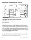
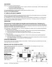
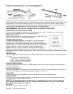
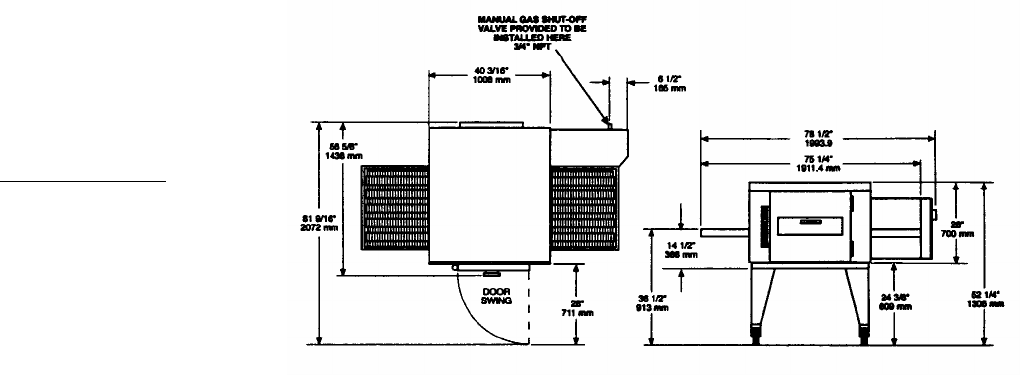
EXTERIOR DIMENSIONS
Gas and electrical services should be located as shown below. If flexible services are provided, they must meet
code requirements for such installation.
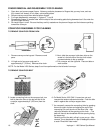
MANUAL GAS VALVE INSTALLATION
When installing the gas valve that is supplied with the oven, as shown in the drawing to the right, it is our
suggestion that an elbow be
placed on the oven pipe first.
This will allow the flexible
hose to be attached in a
downward direction
eliminating possible stress to
the hose.
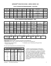
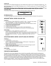
SPECIFICATIONS
Body: Stainless Steel
Power: Gas and/or Electric
DB Level: 71dba
Operating Temperature
Range: 300º - 600º F
(149º - 316º C)