Impinger I -–1000 Series Service Manual - Domestic 35
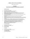
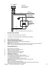
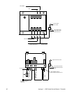
MOTOR
CENTRIFUGAL
SWITCH
RED
RED
24 VAC TO
IGNITION CONTROL
TO GROUND TERMINAL
ON IGNITION CONTROL
GROUND 24 VAC
120 VAC
GREEN
WHITE
BLACK
(BUTTSPLICE CONNECTORS PROVIDED FOR 120 VAC POWER SUPPLY)
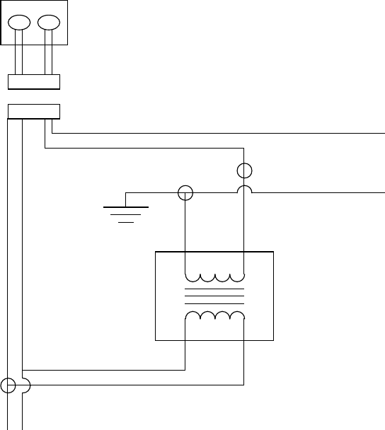
WIRING DIAGRAM
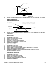
BURNER BLOWER ASSEMBLY
WITH RELAY REMOVED
TRANSFORMER
P/N 369531
(WHEN USING OLD
TRANSFORMER, 120
VAC LEADS ARE BLACK.
WIRE TERMINALS ARE
PROVIDED.)
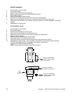
BLOWER WHEEL, BURNER
This is part of the burner blower motor assembly.
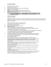
TO REMOVE THE BLOWER WHEEL FOR PERIODIC CLEANING:
1. Shut off power at main breaker.
2. Remove control panel top and front cover.
3. Remove air shutter held by 3 screws.
4. Loosen set screw on blower wheel hub and pull straight out.
5. Reassemble in reverse order.
NOTE: There is no critical placement of the blower wheel on the motor shaft. Just back as
far as it will go and then spin the blower to be sure it is not rubbing.
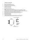
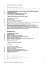
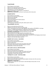
AIR PRESSURE SWITCH
1. Shut off power at main breaker.
2. Remove front control compartment cover.
3. Remove air switch cover plate.
4. Disconnect wiring and mark for reassembly.
5. Loosen 2 screws and remove air switch.
6. Disconnect 1/4" air tube.
7. Reassemble in reverse order.
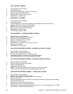
8. Turn on power and calibrate air switch as follows:
Turn adjusting screw counter clockwise to full out position.
Turn main fan and heat switch on.
Turn adjusting screw clockwise until heat shuts off.
Turn adjusting screw counterclockwise 1/4 turn and unit should heat.
NOTE: Test as follows:
Oven must be tested in heated condition.
Remove main fan fuse. Main fan should shut down, deactivating air switch causing
heat to shut off in approximately 5 to 25 seconds.


