


Low Profile – 1600-000-A Advantage Series Service Manual – Domestic
3
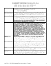
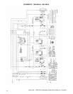
SEQUENCE OF OPERATIONS / 1600-000-A, 1601-000-A
MODEL 1600-000-A / 120 VAC / 60 HZ / NATURAL GAS
MODEL 1601-000-A / 120 VAC / 60 HZ / L.P. GAS
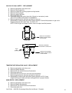
POWER SUPPLY Electrical power to be supplied to the oven by a three conductor cordset. Voltage from
the black conductor to the white conductor to be 120 VAC.
White conductor is Neutral.
Green conductor is Ground.
CONTROL BOX
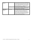
AUTO COOL DOWN
When the temperature in either one of the Control Boxes reaches 120°F ± 3°F (49°C
± 1.7°C), the Cooling Fan Thermostats will switch power to the Cooling Fans. The
thermostats will interrupt power to the Cooling Fans when the temperature falls to
100°F ± 3°F (37°C ± 1.7°C).
MAIN FAN CIRCUIT 120 VAC is permanently supplied to the normally open double pole power switch, a
normally open contact of the oven power relay and the normally open cooling fan
thermostats. Closing the power switch supplies 120 VAC, through the 3 A cooling fan
fuse, through both control box hi-limit thermostats to the coil of the oven power relay.
These normally open contacts now close supplying 120 VAC, through the 10A main
fan fuse to the 2 main fan motors and the 2 burner motors. Power is also supplied to
the cooling fans, the heat and conveyor control systems.
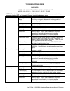
BURNER CIRCUIT Closing the Oven Power Relay supplies 120 VAC to the (2) burner Systems
NOTE: This oven utilizes (2) complete Burner/Temp. Control systems. The sequence
of operations is the same for each system.120 VAC is supplied, through the
Centrifugal Switch of the Main Fan Motor (this switch closes when the Main Fan
reaches approximately 1600 R.P.M.) through the 10 Amp Fuse, to the Ignition
Control, the Electronic Temperature Control, and the burner transformer. As the
Burner Blower reaches approximately 1600 R.P.M., its internal centrifugal switch will
close, supplying 24 VAC to the ignition control. The Ignition Control operates on both
24 VAC and 120 VAC. When the control is energized by 24 VAC, 120 VAC is
switched to the Hot Surface Igniter for 45 seconds for Hot Surface Igniter warm up.
The igniter glows red, 24 VAC is switched to the gas valve which opens, and ignition
should now occur. If ignition does not occur in 6 seconds, the control will lock out. To
recycle after lockout, turn off the burner switch for 45 seconds and then turn the
switch back on.
TEMPERATURE
CONTROL
When the Centrifugal Switch of the Main Fan Motor closes, power is applied to the
Temperature Control. The1K ohm Temperature Pot is adjusted to desired
temperature. Thermocouple will provide varying millivolts to the Temperature
Controller. The Temperature Controller supplies 120 VAC to the solenoid valve at
intermittent intervals to maintain desired temperature. The heat lamp is energized
with the solenoid valve.
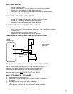
CONVEYOR DRIVE Closing the on/off switch supplies 120 VAC through the oven power relay to the motor
control board. AC volts are converted to DC volts and are supplied to the conveyor
motor at terminals A+ and A-.Adjustments of the speed control potentiometer will
change resistance at terminals P1 and P2 varying the DC voltage to the motor. The
speed of the conveyor motor will increase or decrease as the DC voltage from the
board increases or decreases respectively.
NOTE: The conveyor control uses a sensor and magnet, mounted on the conveyor motor that
senses the motor speed. Any change in motor load, (±RPM) is detected by the
sensor and the voltage to the motor is adjusted accordingly.
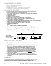
TEMPERATURE
DISPLAY
Closing the switch supplies 120 VAC to the primary of the temperature display
transformer. The secondary of this transformer supplies 12 VAC to the temperature
display. The thermocouple supplies D.C. millivolts to the temperature display. The
display converts this millivolt reading to a temperature reading.