


Low Profile – 1600-000-A Advantage Series Service Manual – Domestic
5
Cooling Fan(s) 120 VAC should be at the motor. If voltage is present, check
motor for shorts, opens, or grounds. WITH POWER OFF:
check for locked rotor.
Gas Supply Check for adequate gas supply and closed manual gas valves.
Also, check flexible gas line connection.
Main Fan If not operating, refer to "Oven fan will not run".
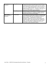
Oven will not heat
NOTE: These ovens utilize 2 complete burner/temperature control systems. Each system will follow the same
troubleshooting sequence.
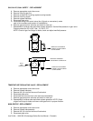
Centrifugal Switch of
Main Fan Motor
Check for 120 VAC supplied to the centrifugal switch, if
voltage is not present, trace the wiring back to the oven power
relay. Check for 120 VAC out of the centrifugal switch. If
voltage is supplied to the centrifugal switch, and motor is
running, but there is no voltage out of the centrifugal switch,
replace the fan motor.
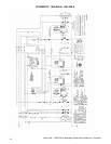
(NOTE: See Schematic Diagram of proper wire numbers on
motors.)
Fuse, Burner 10A Check, replace if necessary.
Fuse holder Check, replace if necessary
Burner Blower Motor Check for 120 VAC supply to the burner blower motor, if 120
VAC is present and motor does not turn, replace the motor.
Burner Transformer Check for 120 VAC to primary of the 24 VAC burner
transformer. If voltage is not present, trace wiring back to the
fuse. If voltage is present, check for 24 VAC at the secondary,
if no secondary voltage is present, replace the transformer.
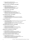
Centrifugal Switch of
Burner Blower Motor
Check for 24 VAC supply to the centrifugal switch of burner
blower motor (see Schematic for proper wire numbers). If no
voltage is present, trace wiring back to the transformer. If
voltage is present, check for 24 VAC at the output of the
centrifugal switch. If there is no output, and the burner blower
motor is running, replace the burner blower motor.
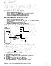
Ignition Control Check for 24 VAC supply to the ignition control at terminals
marked 24V and 24Vgnd. If voltage is not present, trace
wiring back to the centrifugal switch. Check for 120VAC
supply to the ignition control at terminals L1 and L2. If no
voltage is present, trace wiring back to fuse. If the above
checks are okay, proceed. The ignition control should switch
120VAC to the hot surface igniter, across the (2) terminals
marked HIS. If no voltage is present, replace the ignition
control.
Hot Surface Igniter
(Located inside Burner
Assy)
If 120 VAC is present at HSI terminals, visually check to see
that the hot surface igniter is heating (igniter may be viewed
through port glass in end of burner tube). The igniter should
glow bright red. Check all connections to be sure they are
tight. If the igniter does not heat, replace.
Ignition Control After 45 seconds of hot surface igniter pre-heat, the ignition
control will switch 24 VAC to the gas control valves. Check for
24 VAC output from the ignition control, and across terminals
marked "valve" and "valve gnd". If no voltage is present,
replace the ignition control.
NOTE: The ignition control contains a safety lockout circuit. If
a flame is not detected within 6 seconds after the gas control
valve is energized, the ignition control will lockout. To reset,
turn the power switch "off", wait 45 seconds and switch the
system "on" to retry ignition.
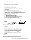
Gas Control Valves Check for 24 VAC supplied to the gas control valves. If
voltage is present, the valves should open. Check for gas
pressure at the pressure tap, located in the gas piping just
prior to the burner. If there is no gas pressure, and the voltage
is supplied to valves, check piping for obstructions. If there