Impinger I -–1000 Series Service Manual - International 32
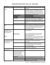
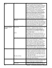
Ignitor/Sensor Assembly Check for visible damage to ignitor/ sensor
assembly. If there is no visible damage to the
components, and no spark, replace the spark
generator. If there is visible damage to the Ignitor
sensor assembly, replace it. Also check for frayed
or damaged wires in burner tube.
Gas Valve Check for 220 VAC supply to gas valve. If no
voltage present, check reset button on ignition
control, check all connections for tightness. If there
still is no voltage at gas valve, replace
No Pilot Solenoid Valve If all above are operating properly, but there is no
pilot flame, check for any obstructions in bypass
orifice (drilled port through wall inside solenoid
valve).
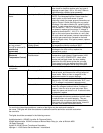
Pilot flame, but burner
will not stay ignited
Flame Sensor (There should be a visible pilot flame at this time.)
To check for flame sensor operation, connect a
digital multimeter (capable of measuring D. C.
micro amperes) between the flame sensor wire and
terminal "F" on the ignition control or in flame
sensor lead for Landis & Gyr. NOTE: this is a
current measurement and the meter must be
connected in series. Proper current readings
should be between 2 and 4 micro Amp. D.C. for
Honeywell, 3 micro amp for Landis & Gyr minimum.
If these readings are not achieved, replace
ignitor/sensor assembly. Also check for any type of
damage to flame sensor wire and connections.
Ignition Control If there is sufficient flame sensor
current, but the burner will not remain ignited,
check reset button on ignition control, if all above
are okay, replace ignition control.
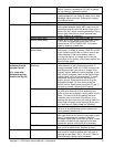
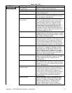
Temperature Control Check for 120 VAC across L1 and L2 on
temperature control board. If no voltage present,
retrace wiring back to power supply. Turn the
temperature adjustment knob to the maximum
temperature position and check for 120 VAC at the
load terminal to neutral. If 120 VAC is not present,
proceed as follows: If 120 VAC is present and unit
is not heating, see "Solenoid Valve."
Thermocouple Probe Remove thermocouple leads from the temperature
control board and measure the millivolt output of
these leads. Refer to chart on page 59 for proper
readings.
Temperature Control
Potentiometer
WITH POWER OFF: remove the leads from the
temperature control board and measure ohms from
black and white leads. The ohm reading should be
0 to 2.5K ohms as the dial is turned through its full
rotation. From black to red leads the reading should
be 2.5K ohms and remain steady throughout the
full rotation of the dial. If the thermocouple probe
and the control potentiometer check good, then the
problem is usually with the temperature control
board.
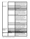
Red indicator light is
on but no main flame
Solenoid Valve If output voltage is present at temperature control
board, check for voltage at solenoid valve. If
voltage is present, listen for valve to open and
close. Also check for opens and shorts in coil.
Replace as needed.


