Impinger I -–1000 Series Service Manual - International 48
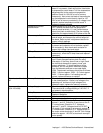
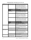
Spark Generator After a pre-purge time of 30 to 60 seconds after
blower motor starts, check for 220 VAC to spark
generator. If voltage is not present, check reset
button on ignition control. If voltage is present,
visually check for spark at ignitor head.
Ignitor/Sensor Assembly Check for visible damage to ignitor/sensor
assembly. If there is no visible damage to the
components, and no spark, replace the spark
generator. If there is visible damage to the ignitor
sensor assembly, replace. Also check for frayed or
damaged wire in burner tube.
Gas Valve Check for 220 VAC supply to gas valve. If no
voltage present, check reset button on ignition
control, check all connections for tightness. If there
is no voltage at gas valve, replace ignition control.
If there is voltage present, check for gas pressure
at gas pressure tap located in gas piping. If there is
no gas pressure, replace gas valve.
If the ignition control is energized, and the gas
valve and ignitor circuits are energized, visually
check for pilot flame. This may be done by opening
the small inspection door on the end of the burner,
or by opening the main oven door and looking
under the lower finger housings on the right side of
the oven. If no pilot flame is visible, check the
following.
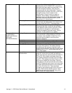
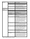
Pilot Tube Check for gas pressure at pilot tube. Disconnect
pilot tube at burner and connect manometer to pilot
tube. If no gas pressure is present, check for
blockage in pilot tube. If these are clear, and there
is gas supplied to the oven, replace the gas valve.
Pilot Orifice If there is gas pressure at the pilot tube, check the
pilot orifice for obstructions. Replace as needed.
No Pilot
Burner Ignitor Check the burner ignitor head for any obstructions,
also check for frayed or broken wire, any type of
damage to spark gap (.100 in 2.5 mm).If there is
visible damage, replace ignitor assembly.
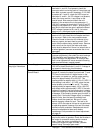
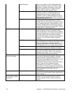
Pilot flame, but burner
will not stay ignited
Flame Sensor (There should be a visible pilot flame at this time).
To check for flame sensor operation, connect a
digital multimeter. (Capable of measuring D.C.
microamperes) between the flame sensor wire and
the ignition control. NOTE: This is current
measurement and the meter must be connected in
series. Proper current readings should be
Honeywell 2-4 micro amp D.C., Landis & Gyr. 3
micro amp D.C. If these readings are not achieved,
replace ignitor/sensor assembly. Also check for any
type of damage to flame sensor wire and
connections.
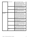
Ignition Control If there is sufficient flame sensor current, but the
burner will not remain ignited, check reset button on
ignition control.
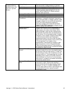
Indicator light is on but
no main flame, (Model
1046-1047)
Gas Control Relay Check for 220 VAC to relay coil. If no voltage is
present, trace wiring back to ignition control. If
voltage is present, check to insure contacts are
closing.


