Impinger I -–1000 Series Service Manual - International 35
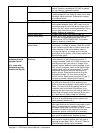
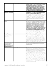
Tach generator and DC Motor
Control Board
With the power to the DC motor control board
turned off, remove the leads from terminals T1 and
T2. Place the test leads of a digital meter on the
tach leads, turn power on, and the meter reading
should be approximately 30 to 35 VDC. This
reading should be steady within ± 0.2 to 0.3 VDC. If
this reading is not within ± 0.5 VDC, place the test
meter probes on terminals A+ and A-. The meter
reading should be approximately 150 to 160 VDC
and steady within approximately 2 VDC. If the tach.
voltage is unsteady, and the board output is steady,
check the coupling for loose set screws or any type
of damage. If the coupling checks good, the tach. is
usually bad. If the board voltage output is unsteady
beyond limits, then the board is probably bad.
Always check the speed pot. be sure it is okay
before changing a board or tach. This test is not
always 100% accurate as this test is not performed
at operating speeds. However, this test is the best
method currently available. Readjustment should
always be attempted at least once before
replacement. See procedure for board adjustment
on page 65.
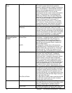
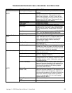
DC Gear motor If the DC control board is steady then the problem
may be the motor or gearbox. Check the brushes in
the motor for excessive arching and/or unusual
wear. Check the motor and gearbox from
instruction located on page 34 under "possible
cause" listing "Conveyor gear motor".
Conveyor will not run
S/N Q14974 & up1000
Series S/N Q14791 &
up 1200 Series
Voltage Supply Check incoming voltage supply at Line 1 to neutral.
There should be a voltage reading of 120 VAC.
Fan Switch See procedure for checking on page 26.
Conveyor Switch Check for 120 VAC to conveyor Switch. If no
voltage is present, trace wiring back to the fan
switch. WITH POWER OFF: Check continuity
between switch terminals.
Conveyor Fuse (3A) Check, replace if necessary.
Fuseholder Check, replace if necessary.
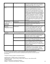
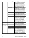
Conveyor Control (Stepper)
Transformer
Check for 120 VAC supply to primary of
transformer, if voltage is not present, trace wiring
back to the fuse holder. If voltage is present, check
for out-put voltage from the transformer secondary.
NOTE: this control transformer outputs (2)
secondary voltages Red Leads 29 VAC Brown
Leads 10 VAC. If BOTH secondary voltages are
not present, replace the transformer.


