


8
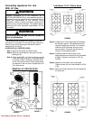
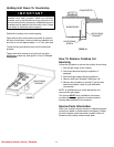
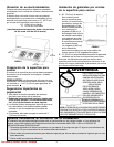
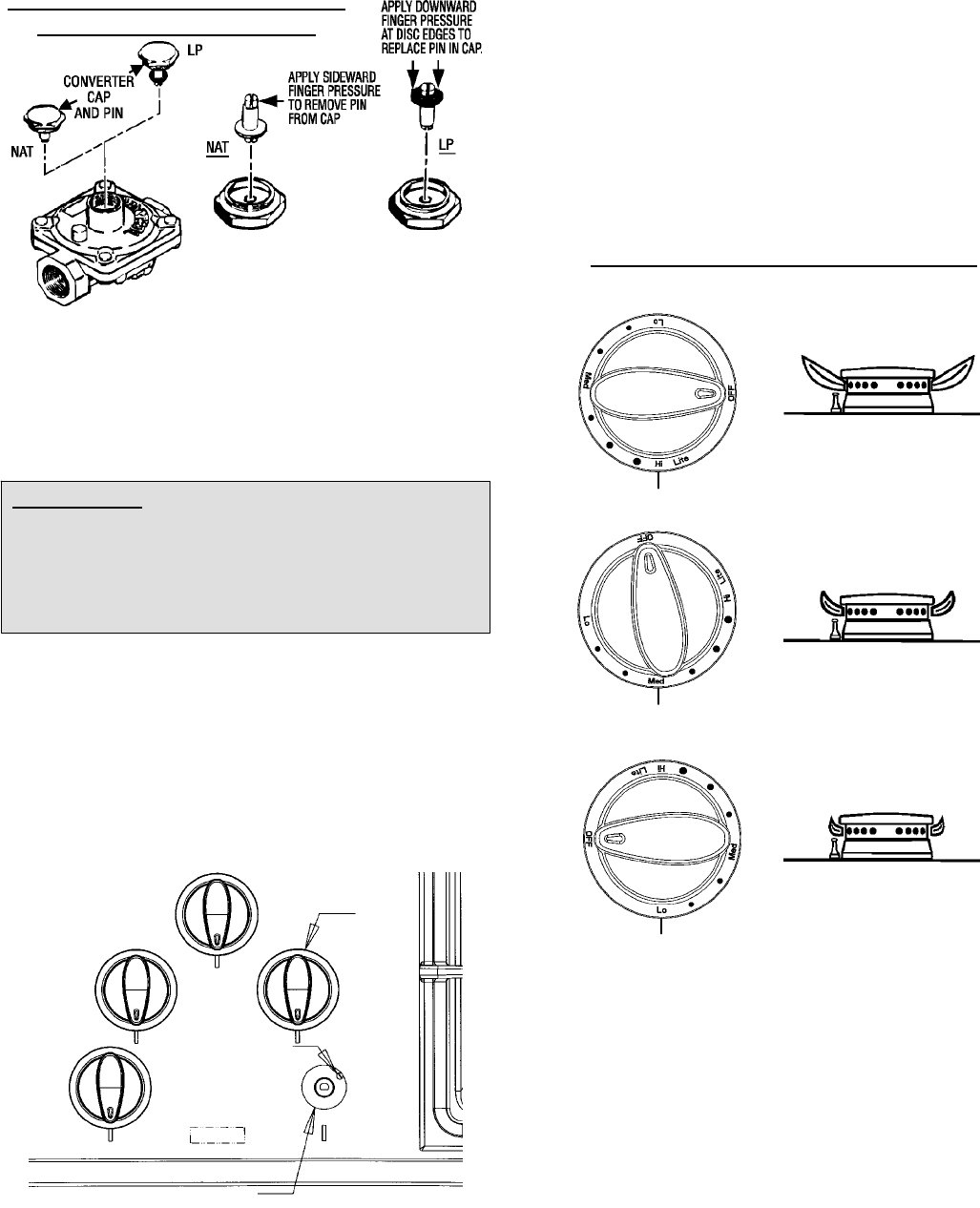
B. INVERT CAP IN APPLIANCE PRESSURE
REGULATOR (See figure 10)
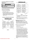
With the appliance installed, the appliance regulator
should be located as shown in figures 3 o r 4.
FIGURE 10
CONVERSION OF APPLIANCE
PRESSURE REGULATOR
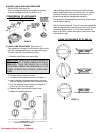
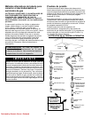
C. LOW FLAME ADJUSTMENT (See figure 11)
This appliance is shipped from the factory with low and
high flame settings adjusted for use with natural gas.
To set for use with LP proceed as follows:
1. Remove control knob from valve stem.
CAUTION: NEVER USE A METAL BLADE TO
PRY KNOB OFF. IF KNOB CANNOT BE EASILY
REMOVED, TUCK THE FOLDS OF A CLOTH
DISHTOWEL UNDER THE KNOB AND PULL THE
TOWEL UPWARD WITH STEADY, EVEN PRES-
SURE.
2. Carefully remove rubber grommet.
3. Locate the valve adjustment screw . See figure 11.
4. Insert a slender, thin-blade screwdriver into knob
hole and engage blade with slot in adjusting screw.
5. Turn the adjusting s crew clockwise until tight (5-7
in-lbs max.). Do not over tighten.
6. Replace rubber grommet and control knob.
7. Repeat for remaining burners.
FIGURE 11
KNOB
ADJUSTMENT
SCREW
KNOB HOLE
(KNOB AND GROMMET REMOVED)
After adjusting the screw the burner should produce a
stable, steady blue flame of minimum size. The setting
should be checked by turning knob from high to low
several times without extinguishing the flame.
This operation will automatically provide the proper flame
size at medium setting.
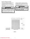
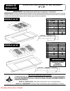
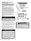
After C onversion Steps A, B and C have been completed,
check the appearance of each burner flame at the Hi and
Lo settings against figure 12. If the flames appear too
large or too small, review each step to make sure it w as
completed correctly.
FIGURE 12
FLAME APPEARANCE AT HI AND LO
Reviewed by Stewart, Steven | Released