


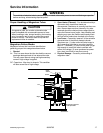

Testing Procedures
!
WARNI NG
To avoid risk of electrical shock, personal injury or death; disconnect power to oven and discharge capacitor
before servicing, unless testing requires power.
©2006 Maytag Services 16026795
21
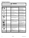
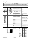
Illustration Component Testing Results
Monitor
Magnetron
Interlock
Switch
Primary
Magnetron
Interlock
Switch
Secondary
COM
NO
NC
COM
COM
NO
Top
Bottom
Bottom
Top
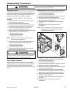
Interlock switch assembly
NC
COM
NO
COM
COM
NO
Monitor
Switch
Primary
Switch
Secondary
Switch
Tab
Tab
Disconnect wires to switch.
With door open measure resistance from:
Monitor – Terminal COM - NC ...............
Primary – Terminal COM - NO...............
Secondary – Terminal COM - NO ..........
With door closed measure resistance from:
Monitor – Terminal COM - NC ...............
Primary – Terminal COM - NO...............
Secondary – Terminal COM - NO ..........
After verifying or replacing the
module, reconnect wires to switch
and check operation of monitor circuit
before operating the oven.
Indicates continuity
Infinite
Ω
Infinite
Ω
Infinite
Ω
Indicates continuity
Indicates continuity
There are two Monitor and
Primary switches. See Wiring
Diagram to identify proper
wiring.
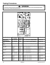
Electronic Control Panel
Service Test Mode: Open door, Press and Hold pad 3 for 5
seconds to enter service test mode.
Press Pad 1 ................................................
Press Pad 2 ................................................
Press Pad 3 ................................................
Press Pad 4 ................................................
Press Pad 5 ................................................
Press Pad 6 ................................................
Press Pad 7 ................................................
Press Pad 8 ................................................
Press Pad 9 ................................................
Press Pad 0 ................................................
Stop/Reset Pad...........................................
SERVICE appears in the display
Indicates number of hours
magnetron has been turned on
Indicates number of times
magnetron tube has been turned
on and off
Indicates number of door cycles
CLEAR (Press START pad to
reset service data.)
Indicates amperage (Top Mag)
Indicates amperage (Bottom
Mag)
RESET (Call Service)
N/A
N/A
N/A
Exit Service Test Mode
Error codes: E-08 ............................................................
E-09 ............................................................
E-10 ............................................................
Replace Control Board
Replace Control Board
Shorted or Open Keypad – Test
and replace if necessary
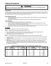
Illustration Component Testing Results
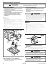
Electronic Control
Keyboard assembly
1
2
3
4
5
6
7
8
9
10
11
Continuity is indicated as
100
Ω and below.
Pad
0
1
2
3
4
5
6
7
8
9
QTY 2X
HOLD (0%)
DEFROST (20%)
MEDIUM (50%)
MED-HI (70%)
TIME ENTRY
STOP/RESET
START
Trace
1 & 8
2 & 8
3 & 8
4 & 8
5 & 8
6 & 8
7 & 8
1 & 9
2 & 9
3 & 8
7 & 9
1 & 10
2 & 10
3 & 10
4 & 10
5 & 10
6 & 10
7 & 10
Measurement
Continuity
Continuity
Continuity
Continuity
Continuity
Continuity
Continuity
Continuity
Continuity
Continuity
Continuity
Continuity
Continuity
Continuity
Continuity
Continuity
Continuity
Continuity