


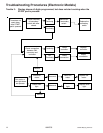
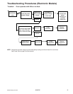
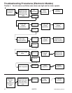
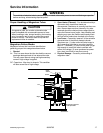

Testing Procedures
!
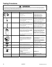
WARNI NG
To avoid risk of electrical shock, personal injury or death; disconnect power to oven and discharge capacitor
before servicing, unless testing requires power.
16026795
©2006 Maytag Services
22
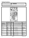
TAB 1
TAB 2
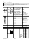
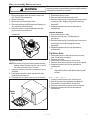
CN1
1
34589
RY3
RY5
1
2
1
2
Function Test Set-Up /
Condition
Meter
Setting
Probe Placement Results
Control power
transformer input
All Conditions Volts CN1 – Pin 3 to Pin 1 (White to Black) 208/230 VAC
Current transformer
input
All Conditions Volts Tab 1 to Power Cord Blue (Neutral) 208/230 VAC
Current transformer
output
All Conditions Volts Tab 2 to Power Cord Blue (Neutral) 208/230 VAC
Oven light
relay RY7
Standby.............
Ready................
Cook..................
Volts
Volts
Volts
CN1 – Pin 4 to Pin 1 (Yellow to Black)..
CN1 – Pin 4 to Pin 1..............................
CN1 – Pin 4 to Pin 1..............................
0 VAC
208/230 VAC
208/230 VAC
Blower / Stirrer motor
relay RY1
Standby.............
Ready................
Cook..................
Volts
Volts
Volts
CN1 – Pin 5 to Pin 3 (Brown to White)..
CN1 – Pin 5 to Pin 3..............................
CN1 – Pin 5 to Pin 3..............................
208/230 VAC
0 VAC
0 VAC
Secondary Interlock
Switch
Door Closed ......
Door Opened ....
Ohms
Ohms
CN1 – Pin 8 to Pin 9 (Pink to Green) ....
CN1 – Pin 8 to Pin 9..............................
< 1
Infinite
Cook relay
RY3
Standby.............
Ready................
Cook..................
Volts
Volts
Volts
Relay 3 – Pin 1 to Pin 2.........................
Relay 3 – Pin 1 to Pin 2.........................
Relay 3 – Pin 1 to Pin 2.........................
208/230 VAC
208/230 VAC
0 VAC
Cook relay
RY5
Standby.............
Ready................
Cook..................
Volts
Volts
Volts
Relay 5 – Pin 1 to Pin 2.........................
Relay 5 – Pin 1 to Pin 2.........................
Relay 5 – Pin 1 to Pin 2.........................
208/230 VAC
208/230 VAC
0 VAC