


Disassembly Procedures
To avoid the risk of electrical shock, personal injury, or death,
disconnect power to oven and discharge the capacitors before
following any disassembly procedure.
WARNING
!
©2006 Maytag Services 16026795 27
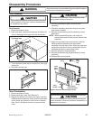
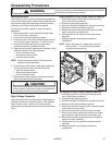
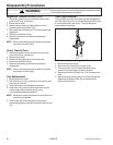
Adjusting Interlocks
The interlock monitor, primary, and secondary switches
act as a final safety switch, protecting the operator from
microwave energy. After adjusting the interlock switch
assembly, verify wires are correctly connected.
For door fit and switch operation, switch bracket is
adjustable.
1. Disconnect power to oven and remove outer case,
(see "Outer Case" procedure).
2. Loosen switch bracket mounting screws.
3. Close oven door, move switch bracket toward rear of
oven until door gap is less than
1
/64–inch (0.5 mm).
4. Hold switch bracket securely for proper switch
operation and door fit, retighten screws.
5. Open oven door slowly, watching the switches. Verify
switches release in the following order.
• Primary interlock switch
• Secondary interlock switch
• Interlock monitor switch
NOTE: Adjust the switch bracket until all switches
operate in proper sequence.
6. Close the oven door slowly, watching the switches.
Verify switches activate in the following order.
• Interlock monitor switch
• Secondary interlock switch
• Primary interlock switch
7. When proper switch sequence has been achieved,
tighten the switch bracket securely.
CAUTION
!
A microwave leakage test must be performed anytime
a door assembly is removed, replaced, disassembled,
or adjustment of switch bracket is performed.
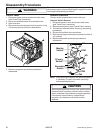
High Voltage Capacitor
High voltage capacitor should always be discharged by
shorting a terminal to a chassis ground. The capacitor
has a internal "shunt" resistor, but the mechanical
discharge should always be performed to avoid personal
injury.
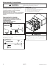
Bottom Magnetron High Voltage Capacitor Removal
1. Disconnect power to oven and remove outer case,
(see "Outer Case" procedure).
2. Discharge high voltage capacitor.
3. Remove and label wire leads from capacitor terminals.
4. Remove screw securing diode to ground.
5. Remove screw securing capacitor strap to the back
panel, located on the back panel.
6. Slide capacitor out of capacitor strap and remove
capacitor.
7. Replace capacitor and reverse procedure to
reassemble.
NOTE: When replacing H.V. components, route H.V.
wires at least
1
/4" / 6 mm from all grounded
surfaces to prevent arcing.
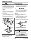
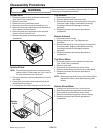
Top Magnetron High Voltage Capacitor Removal
1. Disconnect power to oven and remove outer case,
(see "Outer Case" procedure).
2. Discharge high voltage capacitor.
3. Remove and label wire leads from capacitor terminals.
4. Remove screw securing diode to ground.
5. Remove screw securing top portion of capacitor strap
to the top of the oven cavity.
6. Remove screw securing control panel to chassis.
7. Raise control panel upward and rotate to the side to
gain access to capacitor bottom mounting screw.
8. Remove screw securing bottom portion of capacitor
strap to the duct assembly.
9. Slide capacitor out of capacitor strap and remove
capacitor.
10.Replace capacitor and reverse procedure to
reassemble.