


0
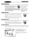
Water Valve Preparation
. . . . . . . . . . . . . . . . . . . . . . . . . . . . . . . . . . . . . . . . . . .
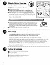
Install a 90” elbow (3/F N.P.T) fitting into the water valve using TeflorP
tape or pipe thread compound. The opposite end of the fitting should fit
in-coming hot water supply line. Position the end of the elbow towards
the rear of the dishwasher.
IMPORTANT: DO NOT
connect a sweat type fitting directly to the water
valve as the required heat will damage the water inlet valve. Do not solder
within 6”
(15.2
cm) from the water valve.
I
Compression Firting
Drain Hose Preparation
. . . . . . . . . . . . . . . . . . . . . . . . . . . . . . . . . . . . . . . . . . .
IMPORTANT:
Routing of the drain hose is most important to insure satisfactory operation. It is not
recommended to extend drain line beyond 7 (2.lm). However, should this be necessary, it must always
be attached to a line of larger inside diameter. An accessory drain hose extension kit (#904204) is available
through your authorized dealer.
DO NOT
route drain hose across the top of the tub, all bends must be
gradual to prevent kinking or collapsing of the hose.
IMPORTANT:
Do not attach the drain hose to any connection smaller than l/2” I.D.
IMPORTANT:
Never cut the corrugated portion of the drain hose. All connections
must be made to rubber portions of drain hose. If cutting of drain hose is required do
not cut past the 5/S” line.
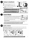
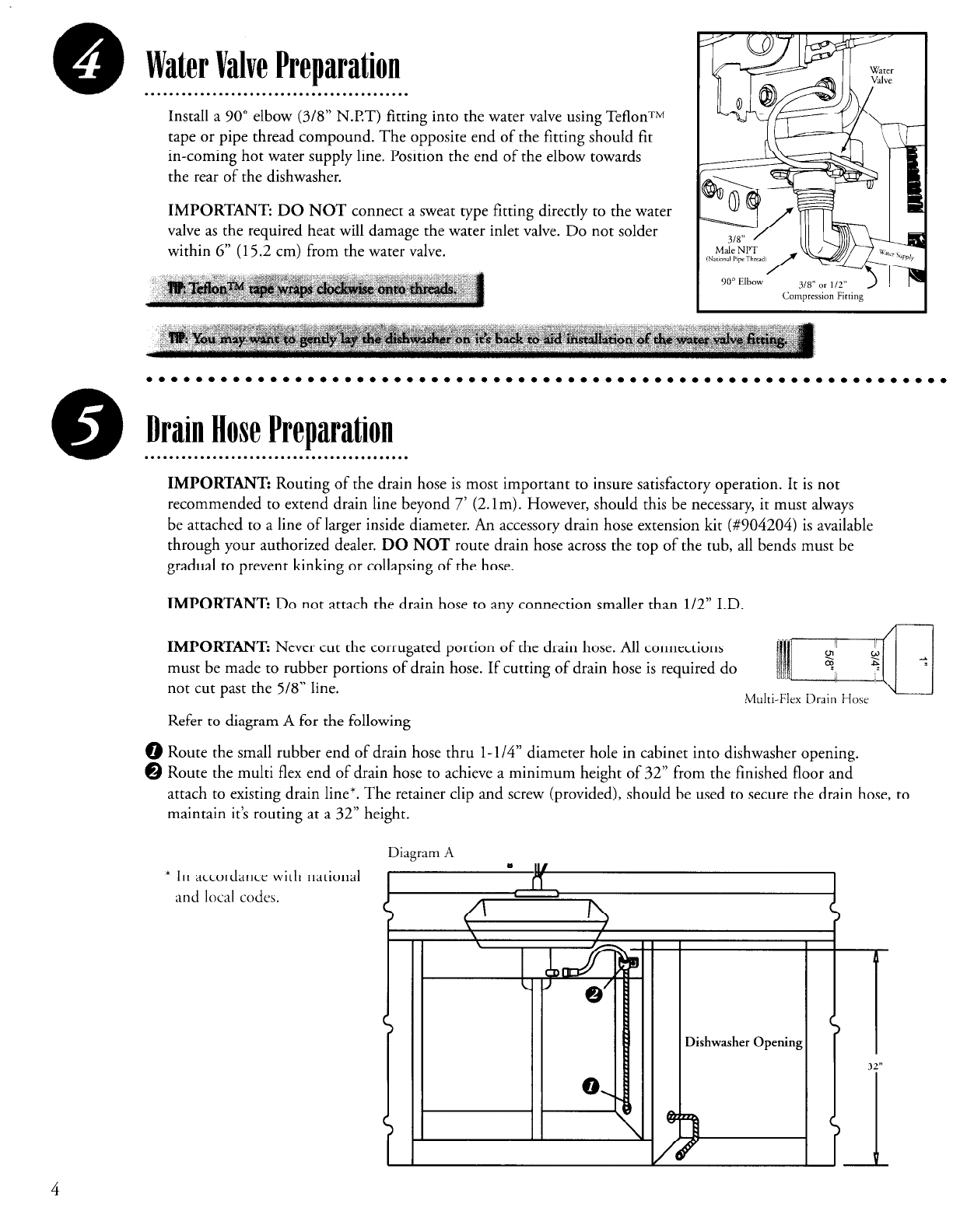
Refer to diagram A for the following
0 Route the small rubber end of drain hose thru l-1/4” diameter hole in cabinet into dishwasher opening.
@ Route the multi flex end of drain hose to achieve a minimum height of 32” from the finished floor and
attach to existing drain line*.
The retainer clip and screw (provided), should be used to secure the drain hose, to
maintain it’s routing at a 32” height.
* In accordance with national
and local codes.
Diagram A
Dishwasher Opening
4