


15
6.0 Installation (cont’d)
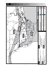
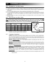
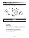
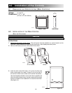
6.4.2 Example of a design for a fully ducted system for a unit having a high
speed performance of 222 cfm
(See figure 9).
VI0004
4” Ø
42 cfm
6” Ø
129 cfm
5” Ø
65 cfm
5” Ø
64 cfm
6” Ø
93 cfm
5”
6”
7”
7”
6”
6”
6”
4”
4”
4”
4”
7” Ø 222 cfm
7” Ø 222 cfm
4” Ø 42 cfm
6” Ø 84 cfm
6” Ø 96 cfm
6” Ø 138 cfm
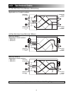
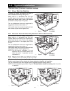
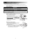
6.5.1 Fully Ducted System (as illustrated in Section 5.1)
Stale air exhaust ductwork:
• Install registers in areas where contaminants are produced: kitchen, bathrooms,
laundry room, etc.
• Install registers 6 to 12 inches (152 to 305 mm) from the ceiling on an interior wall OR
install them in the ceiling.
• Install the kitchen register at least 4 feet (1.2 m) from the range top.
• If possible, measure the velocity of the air flowing through the registers. If the velocity is high-
er than 400 ft/min. (122 m/min), then the register type is too small. Replace with a larger one.
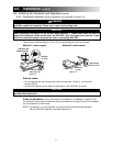
Fresh air distribution ductwork:
• Install registers in bedrooms, dining room, living room and basement.
• Install registers either in the ceiling or high on the walls with air flow directed towards the
ceiling. (The cooler air will then cross the upper part of the room, and mix with room air
before descending to occupant level.)
• If a register must be floor installed, direct the air flow up the wall.
6.5 INSTALLING THE DUCTWORK AND REGISTERS
figure 9
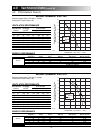
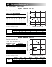
6.4 CALCULATING THE DUCT SIZE (CONT’D)
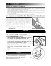
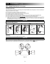
WARNING
010
!
Never install a stale air exhaust register in a room where a combustion device is, such as a gas
furnace, a gas water heater or a fireplace.