


26
WHAT YOU NEED TO BALANCE THE UNIT
• A magnehelic gauge capable of measuring 0 to
0.25 inch of water (0 to 62.5 Pa) and 2 plastic
tubes.
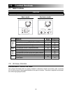
• Two ”Flow Measuring Stations” or two flow
collars (the size will vary depending on the duct
diameter).
PRELIMINARY STAGES TO BALANCE THE UNIT
• Seal all the unit ductwork with tape. Close all windows and doors.
• Turn off all exhaust devices such as range hood, dryer and bathroom fans.
• Make sure all filters are clean (if it is not the first time you balance the unit).
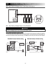
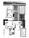
• Make sure the balancing dampers are fully open (F and G in figure 20).
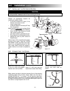
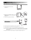
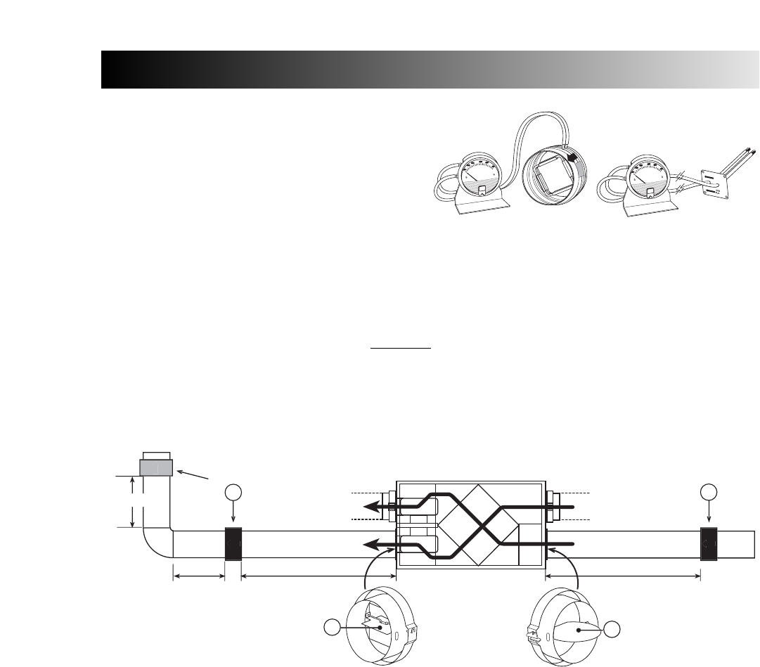
Choose appropriate locations for the 2 flow collars (or flow measuring stations), according to figure 20:
• On the exhaust air duct (first measuring location, A)
• On the fresh air distribution duct (second measuring location, B
• At least 36” away from the unit; at least 12” before or after a 90° elbow; at least 12” away from a
register.
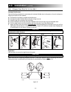
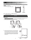
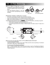
INSTALLATION OF FLOW COLLARS OR “FLOW MEASURING STATIONS”
• If you are using Flow Collars:
Insert the flow collars in the duct at each location. Make sure their arrows are pointing in the direction
of the airflow. Tape collars in place temporarily.
• If you are using “Flow Measuring Stations”:
Cut a 1” (25.4mm) diameter hole in the duct at each location. Insert the “Flow Measuring Stations”.
Make sure their arrows are pointing in the direction of the airflow. Tape the “Flow Measuring Stations”
in place temporarily.
10.0
Air Flow Balancing
VP0005
Flow collar
Flow measuring station
Figure 20
L
O
W
H
W
HIG
H
LO
W
FLO
W
VP0006
1
2
¨
(304mm
)
12
¨
(
3
0
m
m
)
0
4
m
36
¨
(
914mm
)
36
¨
(914mm
)
OR
B
A
G
F
V
P
00
12
A