


23
8.0
Installation of the Controls (cont’d)
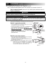
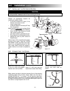
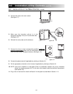
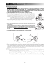
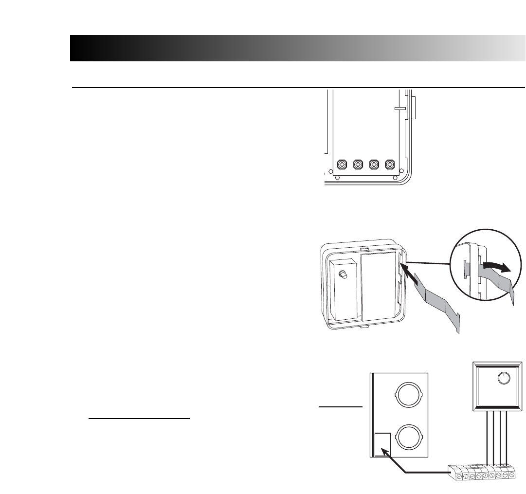
4- Connect the wires to the main control.
(See figure 17.)
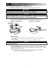
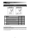
5- Make sure the instruction pull-out is in the
occupant’s language. If not, turn it to the other side.
(See figure 18.)
6- Reinstall the cover plate and the button(s).
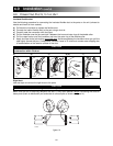
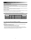
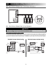
7- Connect the wires to their corresponding position inside the
electrical compartment. Make sure the connections of the unit
and of the wall control correspond exactly. (See figure 19.)
8- Connect the optional control (if applicable) by referring to Section 8.3.
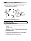
9- Do the appropriate connection to the furnace (if applicable) by referring to Section 8.4.
10- NOTE: If the unit is installed in a cold region (Zone A, as defined in Section 3.0), set up “extended
defrost” by removing jumper JU1F on the main circuit board inside the electrical compartment
(see Section 9.0).
11- Plug in the unit and do the “overall verification” of the system as described in Section 11.0.
Y
R
GB
VD0026
F
F
I
OC
OL
Y
R
G
B
Y
R
G
B
VE0072
VC0061
8.2 INSTALLATION OF THE MAIN CONTROL (cont’d)
figure 17
figure 18
figure 19