


11
Burner Performance
CAUTION: Never cover control knobs or surrounding
control surface with utensils, towels, or other objects.
Never obstruct free air passage past the control knobs.
The knob openings have been sized to p roperly control air
entry to the interior of the appliance during operation.
This appliance has no air shutters. Primary air
adjustments a re unnecessary. The burners are designed
to provide optimum aeration for all gases without air
shutters. When operating properly, burners should
produce clearly defined, even blue flames. If the flames
have yellow tips or are hazy and otherwise appear to
have insufficient air, obtain the s ervices of a qualified
service technician. Some yellow tipping on LP gas is
normal.
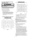
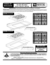
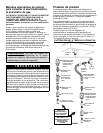
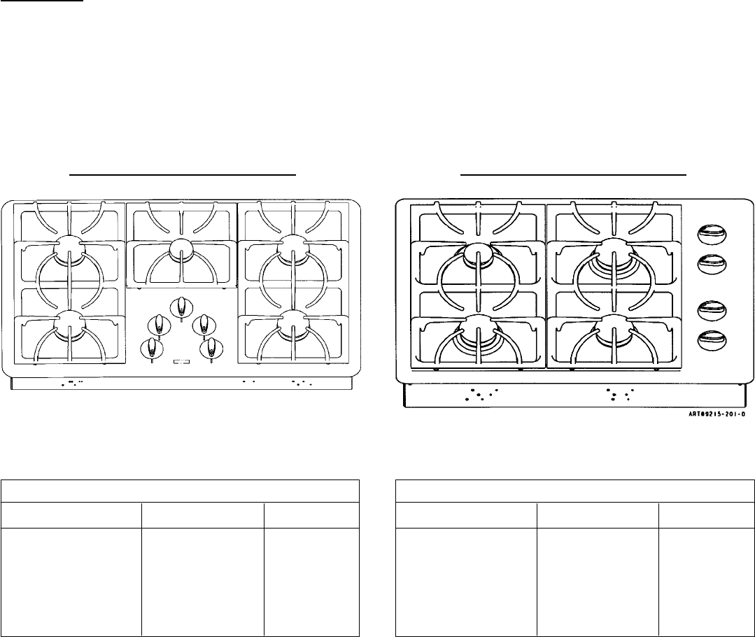
Specified input rates are as shown i n figures 16 and 17
below.
BURNER LOCATIO N Hi Lo
Right Front 12,500 / 10,500 1300 / 1300
Right Rear 9,200 / 9,100 1300 / 1300
Left Front 9,200 / 9,100 1300 / 1300
Left Rear 5000 / 4000 650 / 650
C e nt e r -- -- -- -- -- -- -- -- -- -- -- -- -- -- -- -- -- -- -- -- -- --
INPUT RATES - NATURAL GAS / LP GAS (BTU/HR)
FIGURE 16
5 BURNER MODEL (36²
²²
² Wide)
MAYTAG 30²
²²
²
FIGURE 17
MAYTAG 36²
²²
²
BURNER LOCATIO N Hi Lo
Right Front 12,500 / 10,500 1300 / 1300
Right Rear 9,200 / 9,100 1300 / 1300
Left Front 9,200 / 9,100 1300 / 1300
Left Rear 10,500 / 9,100 1300 / 1300
Center 5,000 / 4,000 650 / 650
INPUT RATES - NATURAL GAS / LP GAS (BTU/HR)
4 BURNER MODEL (30²
²²
² Wide)