


6
Alternative Piping M ethods To
Connect Appliance To Gas Supply
A TRAINED SERVICE TECHNICIAN OR GAS
APPLIANCE INSTALLER MUST MAKE THE GAS
SUPPLY CONNECTION. Leak testing of t he
appliance shall be conducted by the installer
according to t he instructions given.
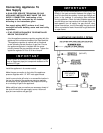
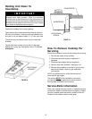
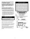
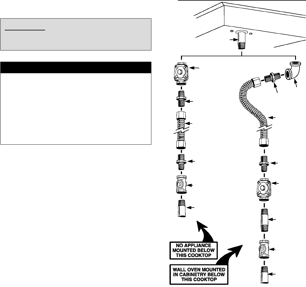
Unless prohibited by l ocal codes or ordinances, a new
A.G.A. - Certified, flexible metal appliance connector may
be used to connect this appliance to its gas supply. The
connector must be no more than 5 feet in length. Per
figure 5, use appropriate flare union adapter at each end
of the flexible connector. If a flexible connector is used
assure that both the appliance pressure regulator and
manual shut-off valve are joined solidly to other
permanent hard piping (either gas supply or the appliance
manifold) so as to be physically stationary. See
illustrations below.
CAUTION: Do not attempt to attach the flexible
connector directly to an external pipe thread.
Connection requires flare union adapters.
IMPORTANT
Apply a non-corrosive leak detection fluid to all joints and
fittings in the gas connection between the supply line
shut-off valve and the range. Include gas fittings and
joints in the range if connections were disturbed during
installation. Check for leaks! Bubbles appearing a round
fittings and connections will indicate a leak. If a leak
appears, turn off supply line gas shut-off valve, tighten
connections, turn on the supply line gas shut off valve,
and retest for leaks. Never test for gas leaks with an open
flame.
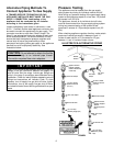
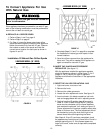
Pressure Testing
The appliance must be i solated from the gas supply
piping system by closing its individual manual shut-off
valve during any pressure testing of the gas supply piping
system at test pressures equal to or less than 1/2 pounds
per square inch (3.5 kPa).
This appliance, as well as its individual shut-off valve,
must be disconnected from the gas supply piping system
during any pressure testing of the system at test
pressures in excess of 1/2 pounds per square inch (3.5
kPa).
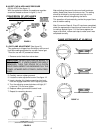
When checking appliance regulator function, make certain
pressure of natural gas supply is between 6 and 14
inches of water column or, if converted for LP gas,
between 11 and 14 inches of water column.
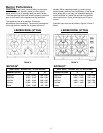
FIGURE 5
ILLUSTRATIVE ALTERNATIVE PIPING
3/8² N.P.T.
Elbow
3/8² N.P.T. Flexible
Appliance Connector
(5 ft. max.)
1/2² N.P.T. Flexible
Appliance Connector
(5 ft. max.)
Appliance Pressure
Regulator, Supplied
(Observe directionality
of Gas Flow)
Flare Union Adaptor
Flare Union Adaptor
Gas Shut-Off Valve
1/2² N.P.T. Pipe
(Stationary Supply Pipe)
Flare Union
Adaptor
Flare Union Adaptor
Appliance Pressure
Regulator, Supplied
(Observe
directionality of Gas
Flow)
1/2² N.P.T. Pipe
Nipple
Gas Shut-Off Valve
1/2² N.P.T. Pipe
(Stationary Supply
Pipe)
Manifold
Entrance