


5
2. IF THIS UNIT WILL HAVE A MAYTAG MODEL
MEW6500 or MEW5500 SERIES ELECTRIC WALL
OVEN INSTALLED BELOW THIS COOKTOP.
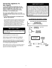
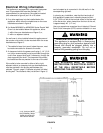
NOTE 1: This appliance and its gas and electrical supply
sources must be installed before the wall oven is installed.
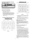
See illustration (Electrical Wiring Information - page 7;
figure 6) for recommended electrical supply source
locations.
NOTE 2: It may be necessary to extend gas supply piping
for this appliance into adjacent under-counter cabinetry
when a wall oven i s installed below this appliance.
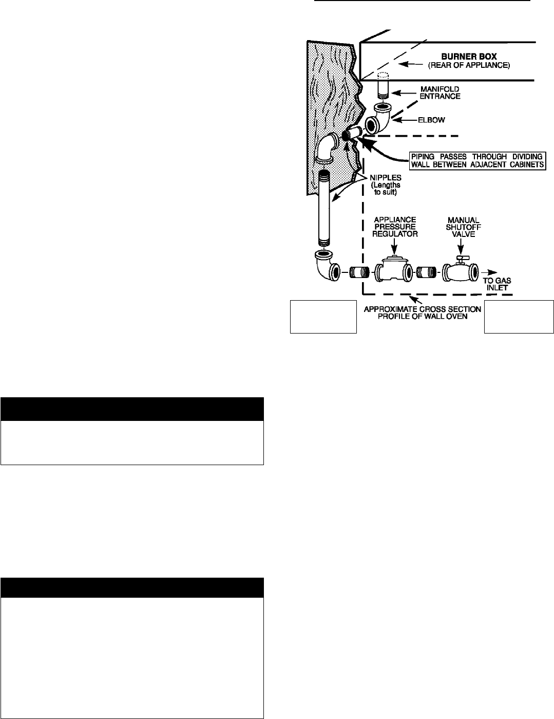
Joina3/8² NPT pipe elbow (locally available) to the male
threads at the manifold entrance. When joined, ensure
open threads of the elbow face toward the right side of
the appliance. Install the appliance in i ts counter cutout.
Joina3/8² NPT pipe nipple to the elbow using a pipe
section of sufficient length to e xtend, horizontally, beyond
the right side of the wall o ven. (To accomplish this i t may
be necessary to extend the pipe section into adjacent
cabinetry.) Join additional 3/8² NPT elbow(s) and pipe
nipples, a s necessary, to accomplish the following:
Join the outlet of the appliance pressure regulator
supplied with this appliance to the male threads of the
newly installed gas supply piping. Install the appliance
regulator in a location which will be accessible beside or
below the wall o ven. Insure the appliance regulator is
installed with its directional arrow pointing in the direction
of gas flow. Tighten the appliance regulator to 20 to 30
ft-lbs of torque.
IMPORTANT
Never tighten to more than 35 ft-lbs o f torque. Always
use an approved pipe joint compound resistant to the
action of LP gas.
Locate and join a manual shut-off valve in an accessible
location in the gas line ahead of the appliance regulator
and external to the appliance for the purpose of turning on
or shutting off gas to the appliance.
Make additional pipe connections as necessary ahead of
the shut-off valve to the gas s upply source. Assure all
pipe joint c onnections are gas tight.
IMPORTANT
Apply a non-corrosive leak detection fluid to all joints and
fittings in the gas connection between the supply line
shut-off valve and the cooktop. Include gas fittings and
joints in the c ooktop if connections were disturbed during
installation. Check for leaks! Bubbles appearing a round
fittings and connections will indicate a leak. If a leak
appears, turn off supply line gas shut-off valve, tighten
connections, turn on the supply line gas shut off valve,
and retest for leaks. Never test for gas leaks with an open
flame.
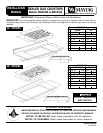
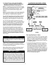
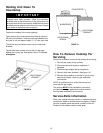
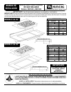
FIGURE 4
ILLUSTRATIVE GAS SUPPLY PIPING
(WALL OVEN I NST AL LED BELOW 30²
²²
² COOKTOP)
(3/8² N.P.T.)
ALL SUPPLY SIDE
PIPE JOINTS
1/2² N.P.T.
ALL UNIT SIDE
PIPE JOINTS
3/8² N.P.T.
Note, regarding Figure 4, above:
S For convenience in service a union (not shown: locally
available) should be i ncluded in the piping illustrated in
figure 4, in a location most practical for the installation.
Generally, a practical location is i n the cabinet below
this appliance, near the manifold entrance, rather than
in an adjoining cabinet.
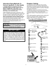
S If the alternative piping method shown i n figure 5 i s
selected for the installation, no union is required. (The
flexible appliance connector illustrated provides the
union joints necessary for servicing.) When a dividing
wall is present and a flexible connector is used it is
recommended for convenience, in both installation and
service, the flexible connector, itself, pass through the
dividing wall. Any flexible connector used with this
appliance must satisfy all requirements stated in
the text accompanying figure 5.