


Testing Procedures
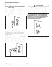
!
WARNING
To avoid risk of electrical shock, personal injury or death; disconnect power and gas to oven before servicing,
unless testing requires power and/or gas.
©2004 Maytag Services 16023415 17
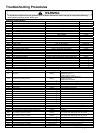
Component Testing
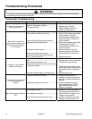
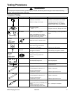
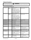
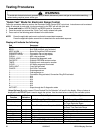
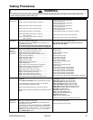
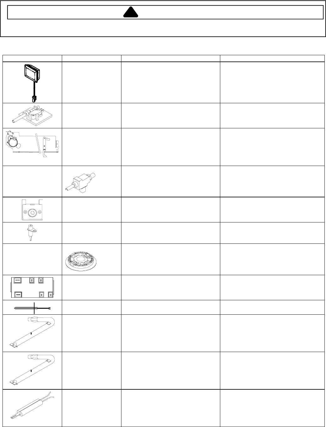
Illustration Component Test Procedure Results
Oven light housing Disconnect connector and test
resistance of terminals.........................
Measure voltage at oven light: .............
Verify bulb is properly installed.
Indicates continuity with bulb installed.
120 VAC, refer to wiring diagram for
terminal identification. If no voltage is
present at light, check wiring/switches.
Door plunger switch Remove switch from unit and measure
the following points:
C NO................................................
Plunger in continuity, Plunger out infinite.
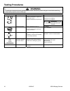
Autolatch assembly
with switch
Disconnect wires and test for
continuity per wiring diagram.
Refer to Parts Manual for correct
autolatch switch associated with the
correct manufacturing number.
See wiring diagram for schematic layout.
Access assembly by removing left side
panel.
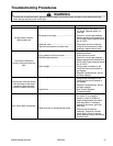
5 K btu
9.2 K btu
16 K btu
12 K btu (Model
MGR6875AD*)
270° valve
Verify gas is supplied.
Adjust set screw for simmer control.
Spark 270° switch
Test for voltage at terminals.................
Disconnect wiring and check for
continuity in LITE position....................
120 VAC
Continuity in LITE position.
Spark ignition
electrode
Test for resistance of spark lead..........
Test ignitor to chassis..........................
Continuity
No continuity from ignitor to chassis.
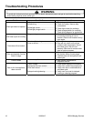
5 K btu
9.2 K btu
16 K btu
12 K btu (Model
MGR6875AD*)
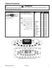
Top surface burner
Verify gas is supplied...........................
Verify burner cap is positioned
correctly.
Check for obstructions in burner ports.
L
AB
A1
B1N
Spark module 4 + 0 Test for voltage at terminals L and N ...
Check polarity and ground...................
120 VAC
See wiring diagram
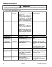
Temperature sensor Measure resistances............................
Approximately 1100 Ω at room
temperature 75°F.
Bake burner Verify gas is supplied.
Orifice adjusted for Natural or LP.........
Check for obstructions or
contamination in ports..........................
Set for Natural Gas from the factory
Adjust as necessary.
Replace if punctured or torn.
Broil burner Verify gas is supplied.
Orifice adjusted for Natural or LP.........
Check for obstructions or
contamination in ports..........................
Set for Natural Gas from the factory
Adjust as necessary.
Replace if punctured or torn.
Ignitor Test for voltage at terminals.................
Test for the amount of amperage in the
circuit...................................................
(Ignitor may glow but not have
sufficient amperage to open valve).
120 VAC
3.2 − 3.6 Amps If not replace.