


24 16023415 ©2004 Maytag Services
Disassembly Procedures
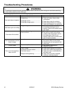
To avoid risk of electrical shock, personal injury, or death:
disconnect electrical and gas supply before servicing.
WARNING!
Moving and/or Replacing Range
1. Turn off electrical power and gas supply to the range.
2. Slide range forward from installation position.
3. Unplug power cord and disconnect gas line from unit.
4. Replace range using Installation Instructions.
NOTE: When placing range into installation position
verify anti-tip bracket(s) are engaged.
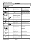
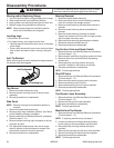
Leveling Legs
• Some floors are not level.
• For proper baking, your range must be level.
• Leveling legs are located on each corner of the base
of the range.
• Place a level horizontally on an oven rack and check
front-to-back and side-to-side. Level by turning the
legs.
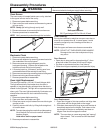
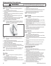
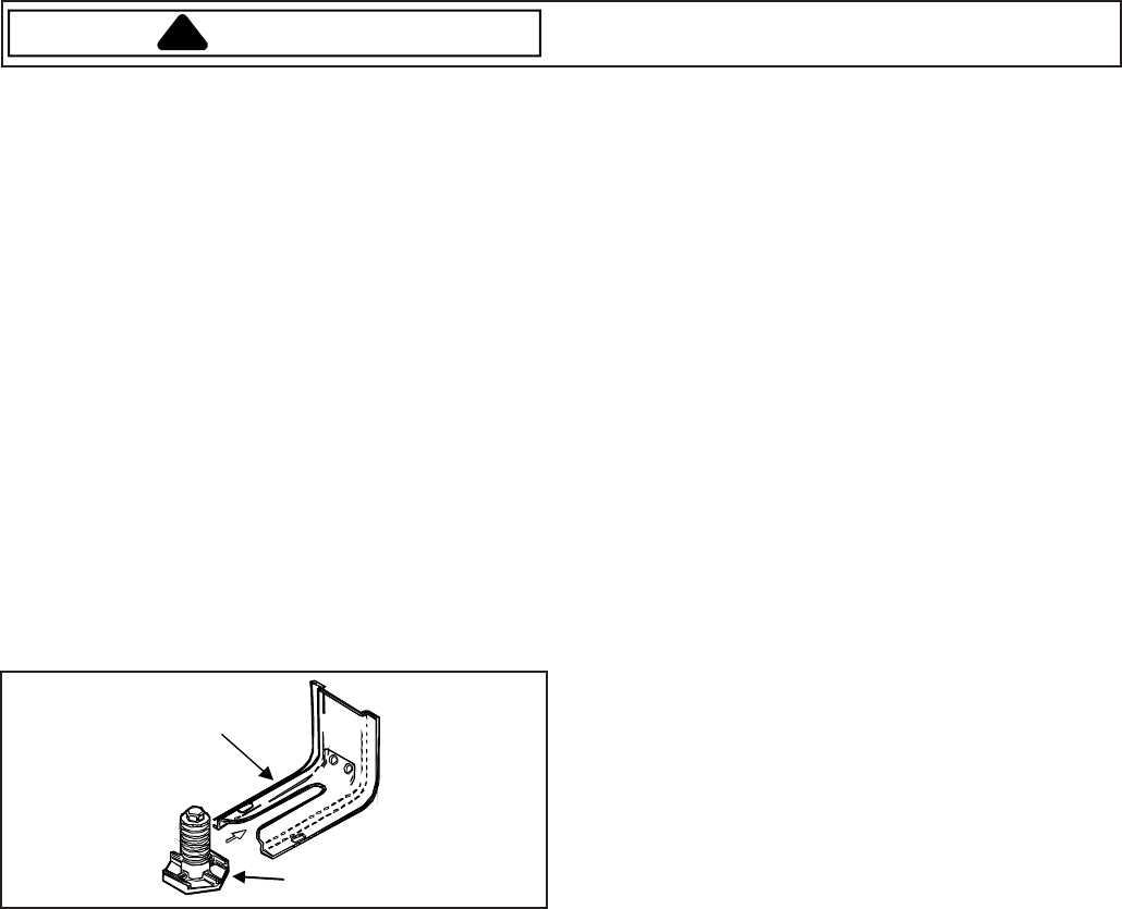
Anti-Tip Bracket
When ever range is moved or replaced for safety reasons
this bracket must be engaged.
Anti-Tip Bracket
Leveling Leg
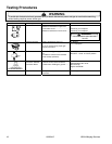
Top Burner
1. Disconnect power before servicing.
2. Remove screws securing burner to burner lower
assembly.
3. Reverse procedures to reassemble.
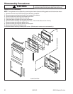
Side Panel
NOTE: Removal of range from installation position is
required.
1. Disconnect power before servicing.
2. Remove range from installation position, see "Move
and/or Replacing Range" procedure.
3. Remove maintop, see "Maintop Removal" procedure.
(Perform steps 1 – 6.)
4. Remove screws securing right side panel at the top
and back of panel.
5. Pull side panel outward away from rear of range,
then lift upward on the side panel to release from
slotted clips located in front and set aside.
6. Reverse procedures to reassemble.
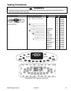
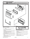
Maintop Removal
1. Disconnect power before servicing.
2. Remove surface burner control knobs by grasping
knob and raising knob straight upward.
3. Remove screws securing infinite switch bracket to
maintop.
4. Remove screws securing burner assemblies to
maintop.
5. Remove screws securing maintop to chassis.
Screws are located in the front left and right corners
with the upper oven door open.
6. Remove screws securing ground strap to chassis.
7. Raise and remove maintop from unit.
8. Reverse procedures to reassemble.
Top Surface Valve and Spark Switch
1. Remove maintop, see "Maintop Removal" procedure.
(Perform steps 1 – 6.)
2. Remove spark switch(es) by pulling upward off valve.
3. Remove wires from spark switch by depressing
release arm.
4. Remove bolt(s) securing surface valve(s) to
manifold. Located on the bottom of manifold.
5. Reverse procedures to reassemble.
NOTE: Perform gas leak test.
Shut-Off Valve
1. Remove maintop, see "Maintop Removal" procedure.
(Perform steps 1 – 6.)
2. Remove screws securing back panel to chassis.
3. Disconnect tubing to shut-off valve.
4. Remove bolt securing shut-off valve to manifold.
5. Reverse procedures to reassemble.
NOTE: Perform gas leak test.
Top Burner Lower Assembly
1. Remove maintop, see "Maintop Removal" procedure.
(Perform steps 1 – 6.)
2. Disconnect tubing from lower assembly.
3. Reverse procedures to reassemble.
NOTE: Perform gas leak test.
Manifold and Top Burner
1. Remove maintop, see "Maintop Removal" procedure.
(Perform steps 1 – 6.)
NOTE: If replacing manifold only, skip step 2.
2. Loosen and disconnect fittings securing surface
burner tubing to burner assembly and manifold.
3. Remove bolt(s) securing surface valve(s) to
manifold.
4. Remove bolt securing shut-off valve from manifold.
5. Disconnect tubing from manifold to the regulator.
6. Reverse procedures to reassemble.
NOTE: Perform gas leak test.