


12
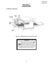
SECTION 2
INSTALLATION
WARNING
DO NOT USE CONDUIT OR GAS LINE
FOR GROUND CONNECTION.
CAUTION
IT IS RECOMMENDED THAT THE OVEN
BE PLACED UNDER A VENTILATION
HOOD FOR ADEQUATE AIR SUPPLY
AND VENTILATION.
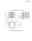
ELECTRIC SUPPLY TO BE
PROVIDED BY CUSTOMER
CIRCUIT BREAKER
Separate circuit breaker with lockout/tagout electrical
shutoff for each oven. Wire each oven separately.
60 Amp circuit breaker for 208-240V 1ph, 50 Amp circuit
breaker for 208-240V 3ph, or 30 Amp circuit breaker for
380-480V.
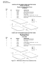
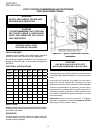
ELECTRICAL SPECIFICATIONS
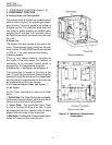
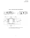
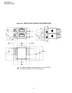
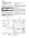
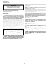
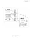
UTILITY ROUGH-IN DIMENSIONS AND POSITIONING
FOR PS528-SERIES OVENS
Figure 2-9. Typical PS528-Series Oven(s)
Installation
Bl o w e r /
el em e nt
208V 240V 380V 480V 280V 230V 240V
P
h a se 3 3 3 3 1 1 1
Ci r Cu i t 208/240 208/240 208/240 208/240 208/240 208/240 208/240
kW 12 12 12 12 10 9.2 10
Fr e qu e n C y 50/60 50/60 50/60 50/60 50/60 50/60 50/60
Po l e s 3 4 4 4 2 2 2
wi r es 4 5 5 5 3 3 2
L1 35.3 30.8 20.2 16.4 48.1 40.0 41.7
L2 35.3 30.8 18.2 14.4 48.1 40.0 41.7
L3 33.3 28.8 18.2 14.4 - - -
N - - 2.0 2.0 - - -
SUPPLY WIRE
Supply wire size must be in accordance with the National
Electrical Code (current edition) and must be in compli-
ance with local codes.
SUGGESTED
If space permits, service should be located near the
control console end of the oven(s) to allow convenient
access to safety switches.
CAUTION
UNIT MUST HAVE AIR VENT PLATES
INSTALLED OR WARRANTY WILL BE VOID.
II. VENTILATION GUIDELINES
A mechanically driven ventilation system is recommended for
the PS528 Series Middleby Marshall conveyorized electric
ovens.
Local codes and conditions vary greatly from one area to
another and must be complied with. Following are the sug-
gested requirements for good ventilation. Please remember
these are recommendations or guidelines, you may have a
special condition or problem that will require the services of
a ventilation engineer or specialist. Proper ventilation is the
oven owner’s responsibility. Improper ventilation can inhibit
oven performance.
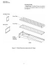
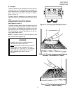
Please Note: There are now two “stand off” ‘C’ Channels
that must be installed in the eld (See Section 6: PARTS
LIST, page 44-45 for reference, Item 5).