


4
SECTION 1
DESCRIPTION
II. COMPONENT FUNCTION (Figure 1-4)
II. COMPONENT FUNCTION
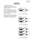
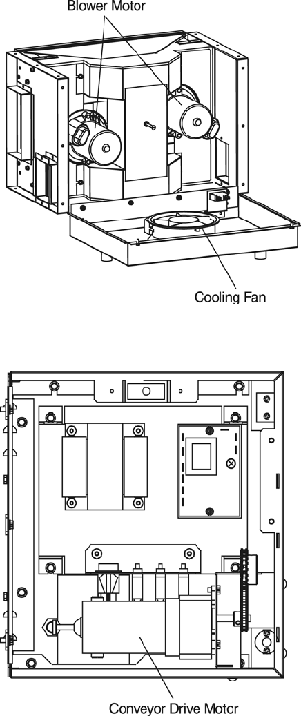
A. Conveyor Motor and Conveyor Belt
The conveyor belt is driven by a variable-speed
electric motor (Figure 1-5) operating through a
gear reducer. The motor speed is controlled by
a digital control. The stainless-steel wire belt
can travel in either direction at variable rates
ranging from 3 minutes to 30 minutes; this is
the time that a product can take to pass through
the oven.
B. Blower Fan
The blower fans are located at the rear of the
oven. These blowers force heated air through
the air ngers. The BLOWER switch must be set
to “ON” or “I” for oven warmup and baking.
C. Electric Heaters
There is one heater element mounted on
the inside of the rear panel. The element is
connected to an electrical control which is
energized by the temperature controller.
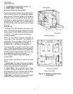
D. Cooling Fan — See Figure 1-5 and Figure 1-6
The cooling fan is located in the back of the
oven. The cooling fan draws air through its grille,
blowing it through the blower motor compartment
and the control compartments into the oven top
and exhausted out the front louvers.
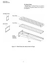
E. Air Fingers and Blank Plates - See Figure 1-7
E1. Air Fingers
An Air Finger Assembly is made up of three
parts:
1. Outer Plate - The Outer Plate is the removable
covering with tapered holes, which direct the air
stream onto the product being baked.
2. Inner Plate -The perforated Inner Plate
is vital in forming the unique air jets. It must
be assembled into the manifold with its holes
aligned with the holes of the outer plate.
3. Manifold - The Manifold is the assembly which
slides on tracks into the oven plenum.
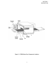
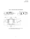
Figure 1-5. Machinery Compartment
Components
Blower Assembly
Right Control Box